Articles
Published
24 years agoon
Densitometry. It sounds complicated–even painful. If you tend to shy away from quality-control devices, the word densitometer might send you screaming into the night. But the next few pages should calm your anxieties and leave you with an appreciation of the role densitometers can play in preventing some of the most troublesome aspects of the screen-printing process.
In a perfect world, you would be able to create artwork, output a film positive, expose a screen, and print the graphic with no loss of image integrity. Unfortunately, the reality is that something usually gets lost when the image progresses from one stage to the next. Dots become larger or smaller. Colors in the printed image don’t match the artist’s intent. And film positives that appear acceptable make stencils that are difficult to process, print, or reclaim.
However, you can identify and control these problems by using densitometers, a solution that’s neither complicated nor expensive. Densitometers give you the power to quantify quality throughout the screen-printing process. Whether you want to control film densities from outside sources, match color proofs supplied by your customer, or spot check color consistency in the middle of a production run, densitometry has a place in your shop. Densitometers can improve prints on any form of substrate, from textiles to compact discs.
If you view densitometers as unnecessary, you are not alone. I estimate that fewer than 5% of all screen printers use them. While other printing processes, such as offset lithography and flexography, have always relied on densitometers, most screen-printers continue to visually inspect film positives and printed images. But times are a-changin’.
Other printing processes, including digital alternatives, are competing for a share of screen printing’s traditional markets. Since these technologies rely on quantifiable densitometer measurements to achieve quality prints, you owe it to yourself to adopt the same technology. A densitometer will enable you to tackle the most challenging jobs with confidence and ultimately leads to more profitable printing. For screen-printing shops of any size, a densitometer should be as commonplace as a tension meter or exposure calculator.
Densitometer types
Densitometers are available in two varieties: transmission for reading film positives and reflection for reading printed images.
Transmission densitometers are used to assure the light-stopping densities of the film positive and control the consistency of the image output. A transmission densitometer measures the opacity of the image and transparency of non-image areas of the film, telling you whether it will block and transmit enough light to produce a good stencil. The densitometer also measures the tonal range and degree of dot gain in halftone film positives. Uncontrolled dot gain in CMYK film separations will lead to poor color reproduction when the four colors are combined in the printing process.
Reflection densitometers measure reflected light and are used to gauge color densities of original artwork, photos, proofs, substrates, and printed images. A reflection densitometer can be indispensable in helping you judge the ink deposit of your prints or solving ink mixing (pigment ratio) problems that lead to shade variances during long print runs. It also distinguishes hue differences by measuring the ratio of CMYK values and detects if any of the inks are over or under strength by identifying problems with gray balance in the 100% coverage areas. Additionally, the device will help you compensate for substrate characteristics. If the material features a different gloss, porosity, or shade than the original or initial prints, the reflection densitometer provides numerical data that enables you to compensate for the differences during art creation, film generation, or screenmaking.
How densitometers work
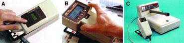
Densitometers are available as combination units or as individual transmission or reflection devices. I prefer the individual gauges because of their portability and ease of use. Cell-charged and battery-operated gauges are available that can be carried from the art department right out onto the pressroom floor. More importantly, today’s densitometers are simpler to operate than earlier models, displaying data without the need for manual calculations or separate readings of individual colors.
Functionally, a densitometer is a gauge that shines a light on a film positive, sample photograph, or printed piece, and measures the amount of light that is either transmitted through film or reflected from a substrate under specific conditions. The best way to describe a densitometer’s simple mechanical operation is to compare it to a hand stapler. The shape is similar, with its back pivot point, as is its operation. You simply press and hold a button to take a reading. The exact measurement will appear automatically on the display screen at the top of the gauge. Once you have the reading, you can feed the information back into the various areas of the production process, where adjustments can be made.
Practical applications: Transmission densitometers
As I’ve stated, transmission densitometers are used primarily to determine the density of a film positive, providing numerical measurements of the film’s opaqueness and transparency. The two primary measurements you’re concerned with are the Dmax (maximum density) and Dmin (minimum density) of the film.
Stencil exposure, Dmax, and Dmin — Most screen printers recognize the effects of stencil underexposure: pinholes, stencil breakdown, image scumming, poor edge quality, and difficult screen reclaiming. Underexposure is often associated with light sources, emulsions, and exposure testing, but frequently the source of the problem is the film positive itself. The best film positive will offer maximum density in the image areas and the minimum density in the non-image areas, which is why we need to look at Dmax and Dmin values.
The Dmax value represents image density. It is equal to the maximum density that a particular film positive material will provide, whether the positive is produced photographically or from a digital device such as a laser printer or thermal imagesetter. When selecting a densitometer, the higher the Dmax value the gauge is capable of measuring, the better. A value of 6.0 is ideal.
For screen printing, the film’s Dmax should be 3.0 or higher. As the Dmax drops below 3.0, light will be transmitted through the image areas, progressively hardening the emulsion in areas of the stencil that should remain clear, which will make it difficult to process the image accurately. After you wash out the “fogged” image area, you may end up with poorly developed fine lines or jagged stencil edges. In relation to half-tone dots, low Dmax could also contribute to moiré.
Dmin is used to measure the light-transmitting ability of clear, non-image areas of the film. Equal to the lowest density on the positive or negative, the Dmin value ideally should be below 0.1. A high background density will block light that is needed to crosslink the emulsion, resulting in stencil underexposure. A normal-quality film positive will have a Dmin of 0.06. If you add a piece of transparent tape or double the thickness of the film positive, you automatically bump the Dmin up to 0.1-0.12.
Laser-imageable materials, such as vellum and similar specialty films, are of special concern. Their translucency and correspondingly high Dmin values restrict or slow light from passing through non-image areas, leaving the stencil underexposed. You must compensate for these limitations by making exposure adjustments that allow enough light to penetrate the translucent areas and cross-link the emulsion without overexposing finer details. If you can’t live with a significant increase in exposure time, select a laser-imageable material with the lowest possible Dmin value.
The Dmax value of any laser material is dependent on the laser printer itself, but it is unlikely that you will ever obtain a density reading of 3.0, even if you post-treat the positive with heat or special sprays. For best results with laser-imaged positives, test several types of vellum and film on your laser printer, measuring and recording the Dmin and Dmax values. Then select the solution that requires the least amount of compromise.
Image areas produced on thermal imagesetting film are often a transparent black or reddish-black. This might lead you to think that they don’t provide enough density for good screen exposure. The opacity is not as important as the light-stopping abilities of the image’s color. Thermal films will generally produce a very acceptable Dmax value, but the only way to gauge their true densities is by using a transmission densitometer.
Digitally imaged positives aren’t the only ones that can suffer from insufficient density. Orthochromatic films and imagesetter films also can be affected by processing temperature and the age of the processing chemicals.
Dot area and dot gain — Halftone images consist of dots and the clear areas that surround them. The percentage of the area made up of these dots is known as the “percentage” of dot area. However, dot size may change during processing and create a condition known as “dot gain,” which is measured as the difference in size between the original dot and the reproduced dot.
Although dot gain is an accepted occurrence in all printing technologies, it is particularly problematic for screen printers. Your processing steps must be consistent and well controlled in order to predict and compensate for this phenomenon. If you don’t control dot gain, the result will be reduced tonal range, color variances throughout the image, and loss of detail.
Dot gain can occur in three areas of production: film processing, screenmaking, and printing. The first and last areas are where densitometers come into play–a transmission densitometer is used in film processing and a reflection densitometer is used during printing, which I’ll discuss later.
The first opportunity for a dot to change size occurs during the conversion from artwork to film, whether the film positive is processed photographically or digitally. The characteristics of your output device or processing methods will influence the amount of dot gain and overall dot quality of the film.
In camera processing/developing or diffusion-transfer processing, the freshness of the developing chemicals will affect not only the density of the image, but also the sharpness and size of the dot. Camera accuracy in reproducing the original artwork is another critical factor. These variables point to the importance of using a transmission densitometer to provide a baseline check of the dot area on your film.
With digital output devices, you are not concerned with processing chemistry or camera accuracy. However, you need to consider the different ways that imagesetters deposit dots on film. A laser printer deposits toner, which can scatter, creating a corona effect around a dot. A thermal imagesetter uses heat to create the image. Excessive heat can make the image “bloom” or expand. In the rare instances where inkjet printers are used to produce film positives, the ink must hit the media with a minimum of splatter. This is a function of printhead technology, ink chemistry, and the ink receptivity of the media. But regardless of the type of output device, the dot sizes can change as the printheads age. Monitoring digitally produced film positives with a densitometer will alert you to these changes as they occur.
Practical applications: Reflection densitometers
To be technically correct, densitometers cannot be used to actually measure color. In order to measure color, two different instruments are required: a spectrophotometer and a colorimeter. The spectrophotometer measures the actual or physical absorption characteristics of color. The colorimeter measures color as it is seen and processed by the human eye.
Although a reflection densitometer does not measure color per se, it provides data you need to make accurate comparisons and color corrections. With this device, you have the advantage of relying on quantified base readings, rather than on subjective visual inspections.
Similar to the transmission densitometer, the reflection densitometer measures optical density. The light reflected back to the device is broken into CMYK (cyan, magenta, yellow, black) segments of the visible spectrum using red, green, and blue filters. These color components are then translated logarithmically into useful values. Some newer reflection densitometers provide an automatic reading of the predominant color, along with a breakdown of the remaining three colors for comparative purposes. These units are menu-driven and automatically calculate color reflection density, black-and-white reflection density, density differences, dot area, and dot gain. A density reading of 0.00 means that 100% of the light hitting the sample is being reflected, and a reading of 1.00 means that 10% of the incident light is being reflected.
A reflection densitometer can also be used as an aid in monitoring ink-film thickness. It cannot be used to actually measure the thickness, but it can indicate the print’s opacity level, which is helpful maintaining color consistency during long print runs. For example, your 100th print might give you a densitometer reading of 57%, but the 200th print could read 45%. Since the change occurred on press, you know the film positive and stencil are not the sources of the problem. So you need to check the press settings or ink characteristics. If you print the entire job without density checks, you’ll see color shifts and similar variances during production and washed-out images when the job is complete. By maintaining a consistent ink density reading, you can be assured that the ink deposit will remain the same. If the density reading varies either up or down, you can assume the ink deposit has also changed.
Keep in mind, reflection densitometers are not limited only to process-color work. Spot color jobs can benefit just as much from the use of a densitometer. Simply take densitometer readings from drawdown swatches of the ink that will be used to print the job. Then take readings of the printed image periodically throughout the run to highlight any changes in ink deposit.
Hue error and gray balance Some reflection densitometer models also provide readings for hue error and gray balance. These values are used as checkpoints for comparing the spot- or process-color inks used to print a job against the proof or match print provided by the customer.
In simple terms, a hue is a color (e.g., orange, violet, green). But more specifically, hue represents a combination of process colors (CMYK) that produces a specific shade or tint of a color. Once you define the base-color breakdown of your prints, you can use the densitometer to measure any variance in hue (a.k.a. hue error), then adjust your film positives to correct the error.
Gray balance represents how contaminated or dirty the primary ink color is based on the amount of complementary color (get your color wheels out) it contains. The more complementary color contained in the primary, the higher the gray value and the greater the “muddy,” gray, or dirty appearance of the primary. In a perfect world, cyan, magenta and yellow would have gray-balance values of zero. But in reality, all inks have some gray value. Densitometers that provide data on gray balance can help identify problem colors so that you make corresponding adjustments in the film positives to compensate.
Monitoring dot gain — The final print itself will yield a different dot size (as compared to the dot size on the film positive or exposed screen) because at least as many variables exist in printing as in film or stencil processing. Other than press settings, factors that contribute to dot gain include ink rheology (flow characteristics), substrate absorbency, and whether the ink dries by evaporation or is cured onto the material.
Press setup is also a major factor. Squeegee speed, angle, and pressure all control the hydraulics of the ink as it is pumped through the mesh opening, which influences ink deposit. Dot gain of more than 30% may result if the squeegee smashes the ink through the mesh, rather than shearing it cleanly.
Figure 2 shows a film positive for a 133-line halftone with a 50% dot area and dot size of 125.4 microns. (Note: For ease of explanation, this halftone uses a square dot. But an elliptical dot is generally preferred for screen printing because it offers a smoother graduation of tones, especially in the mid-tone range.) This positive was used to correctly expose the stencil shown in Figure 3, which has a 123.7-micron stencil openings. When the stencil was used to print an image on medium absorbency paper stock, the printed dot size was 149 microns. The same film positive was also used to produce both underexposed and overexposed stencils, creating respective stencil openings of 124.6 and 120.7 microns, which produced printed dot sizes of 159 and 141 microns.
Although stencil-opening size differs slightly among the three stencils, this example illustrates the amount of exposure latitude the emulsion provides when it’s under and overexposed. You also may be wondering why the dot size of the final print varies so much from the film positive. The answer is substrate absorbency, something you would not be able to determine quantitatively without using a densitometer.
The point of this comparison is to illustrate that 1) dot gain varies depending on the processing conditions, and 2) without quantitative data, you will not be able to clearly define and compensate for dot gain. When unanticipated, a few microns difference between the dot size on the positive and on the exposed stencil can significantly shift the hue of the print–so much that you may need to expose new screens.
Substrate absorbency also contributes to dot gain. Consider the differences in dot shape and size when the screen shown in Figure 3 is used to print on absorbent stock (Figure 4 top) versus non-absorbent stock (Figure 4 bottom). You can clearly see the loss in dot sharpness and increase in dot gain on the absorbent substrate. But note how cleanly the ink “sits up” on the non-absorbent substrate (polycarbonate in this example).
Using the data
A densitometer doesn’t solve problems by itself. You have to use the data to make necessary adjustments in film output, screenmaking, and printing.
Densitometers probably provide the greatest benefit when you try to compensate for density variations in your film positives. With photographic film generation, you can use densitometer data to adjust processing procedures and chemistry. And with digital film output devices, particularly imagesetters, adjusting output based on densitometry readings is even easier. Most imagesetters can use the software that drives them to automatically adjust their output based on Dmax, Dmin, dot-area, and dot-gain measurements provided by a densitometer. Some newer densitometers even interface directly with popular RIP programs and color-management applications.
During a press run, densitometer readings can be used to highlight inconsistencies in many production variables. Such inconsistencies could include problems with stencil exposure in screenmaking or any number of ink and setup parameters on press.
From one end of the screen-printing process to the other, measurement is the key to control. By using a densitometer, you’ll get the hard data you need to correctly adjust the process and consistently produce quality prints.
Frank Basch is the technical manager for Majestech Corp., Somers, NY. With extensive experience in screen printing, he often contributes technical articles and expertise to industry publications. He is also a frequent speaker at the Screenprinting & Graphic Imaging Association’s annual tradeshow.
Special thanks to Tobias Associates, Inc. for providing technical data on densitometry and California University of Pennsylvania for allowing use of its screen-printing facility.
Densitometer Manufacturers
Gretag-Macbeth 617 Little Britain Rd. New Windsor, NY 12553-6148 914-565-7660 800-622-2384 fax: 914-561-0267 Web: http://www.macbethdiv.com
IHARA 25030 Tibbits Ave., Bldg. K Valencia, CA 91355 805-257-5772 800-457-8059 fax: 805-257-5880 E-mail: keithlca@aol.com
Tobias Associates, Inc. 50 Industrial Dr. PO Box 2699 Ivyland, PA 18974 215-322-1500 800-877-3367 Fax: 215-322-1504
X-Rite Inc. 3100 44th St. SW Grandville, MI 49418 616-534-7663 fax: 616-534-8960 Web: http://www.x-rite.com


Subscribe

Magazine
Get the most important news
and business ideas from Screenprinting Magazine.
Most Popular
-

 Art, Ad, or Alchemy1 month ago
F&I Printing Is Everywhere!
-

 Case Studies1 month ago
High-Density Inks Help Specialty Printing Take Center Stage
-
 Andy MacDougall1 month ago
Functional and Industrial Printing is EVERYWHERE!
-

 Columns2 weeks ago
8 Marketing Mistakes Not to Make When Promoting Your Screen Printing Services Online
-

 Editor's Note2 weeks ago
Livin’ the High Life
-

 Thomas Trimingham2 months ago
“Magic” Marketing for Screen Printing Shops
-

 Marshall Atkinson2 weeks ago
How to Create a Winning Culture in Your Screen-Printing Business
-

 News & Trends1 month ago
What Are ZALPHAS and How Can You Serve Them in Your Print Business?