Articles
Published
20 years agoon
Last month, we considered the conditions and procedural errors in screenmaking that can lead to obvious pinholes before screens ever leave the screenroom. But even if a stencil appears sound when it leaves prepress, this is no guarantee it will remain that way throughout the production run. Stencils can fail on press for a number of reasons other than those we attribute to prepress pinholes. This installment identifies the three main causes of pinholing on press–chemical breakdown, mechanical breakdown, and improper stencil-coating technique–and explains procedures to help overcome them.
Chemical breakdown
Chemical breakdown is a reaction between the emulsion and another chemical that causes the emulsion to change its chemical structure. Chemical breakdown is apparent when the emulsion becomes extremely tacky and begins to soften. It also may change back to the color it was prior to exposure. When the stencil shows these characteristics, it means that inks, solvents, or cleaners have attacked the emulsion and changed its chemical makeup and physical properties. Chemical breakdown has three primary causes: using an inappropriate emulsion, too much moisture in the stencil during exposure, and improper exposure.
Using an inappropriate emulsion for the job Printers like to keep things as simple as possible in the screenmaking department. So many try to use a single type of emulsion for a multitude of printing applications. However, this practice occasionally may cause printing nightmares because the emulsion does not live up to expectations and begins breaking down prematurely. This leads to prolonged down time on press and/or excessive time and material costs because extra sets of screens have to be made to complete the job. Scrap rates also multiply due to the premature breakdown of screens.
All emulsions are not created equally. Each type of emulsion–diazo sensitized, diazo-photopolymer sensitized (dual cure), SBQ sensitized (pure photopolymer)–has uniquely different characteristics. Manufacturers formulate emulsions to fulfill many criteria on a scale of more or less: solvent resistance, water resistance, abrasion resistance, elasticity, durability, resolution, exposure latitude, exposure speed, ease of reclaiming, etc.
A prerequisite for selecting the right emulsion for trouble-free printing is a good understanding of the job requirements. For example, what type of inks and additives will be used? Are they abrasive in nature? What type of solvents will be used for cleanup? What type of substrate does the job call for? Is it flat or contoured, rough or smooth? How many pieces will be printed? What kind of detail is required, and what mesh count(s) will be used? All of this information will help you pick the emulsion best suited for the job.
Most emulsion manufacturers have screen-printing application guides to assist you with your selection. If you are unsure if the emulsion you use is up to the task, contact your local distributor or the manufacturer for help.
Too much moisture in the emulsion during exposure If the emulsion is not thoroughly dried prior to exposure, residual moisture in the emulsion will interfere with the exposure process and can lead to premature breakdown on press. Interestingly, the length of time an emulsion has dried is somewhat irrelevant. What is relevant is the amount of moisture in the emulsion at the time of exposure.
For example, if screens were coated on Friday afternoon and exposed the following Monday morning, you might assume the screens were plenty dry. Be careful not to make this assumption. If you have no temperature or humidity controls in your screen-drying room and returned to work on a cold, rainy January morning, would your screens be dry? They may be dry to the touch, but if the humidity in the screen-drying room is 75%, technically those screens are not dry.
Until screens are exposed, they are very hygroscopic, which means they readily take up and hold moisture. So if the humidity is high where they are being stored, then the emulsion will have the same amount of moisture as is in the air. Therefore, the screens will not be dry enough to expose properly without fear of premature breakdown during printing.
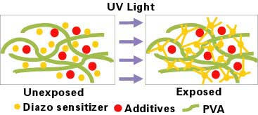
As illustrated in Figure 1, during exposure of a diazo-sensitized emulsion, the diazo crosslinks with the polyvinyl alcohol (PVA) to form a hardened stencil. Once the screens are exposed, developed, and dried, most emulsions are humidity resistant. Figure 2 illustrates how the chemical crosslinking is hindered if there are too many water molecules present in the emulsion at the time of exposure, regardless of how much exposure time is used. When the screen is washed out, unreacted components of the emulsion will rinse off the screen and leave a weak stencil susceptible to pinholes and premature breakdown.
With this understanding, we can set up our screen-drying area with heaters, dehumidifiers, hygrometers, and ventilation systems to monitor and regulate the temperature and humidity year round. This way we won’t be bothered by seasonal productivity slumps when we seem to have more emulsion-related printing problems (usually every summer as the humidity rises).
The drying area should be maintained at a constant 35-45% relative humidity. In many shops, this will require using heaters, dehumidifiers, and some sort of ventilation system. Dehumidifiers compliment heaters by pulling moisture out of the air. Air circulation also is helpful, and an exhaust fan to help pull moisture-laden air from the room completes the system. Temperature and humidity are easily monitored with the use of a thermometer and hygrometer (to measure relative humidity) placed on the wall or inside the drying cabinet.
Equipping the drying area in this way does not have to be expensive. If the room is small, a small space heater, dehumidifier, and simple ceiling exhaust fan should not cost much more than $200. A hygrometer costs as little as $30 at Radio Shack.
With a dedicated drying cabinet or closet, the temperature can be increased to as much as 100°F (38°C) for even faster drying. Just keep in mind that coated screens should not remain in a heated drying cabinet for very long because the emulsion will begin to crosslink when exposed to elevated temperatures for extended periods.
Air conditioners also can be used to help dehumidify the air. However, heaters are more efficient because warm air attracts a greater amount of moisture than cool air. The moisture’s attraction to the warm air helps pull it out of the emulsion. Air conditioners are best utilized when setting up a separate storage area for screens that are going to be stored for some time before exposure–cool, dry air is preferred for screen storage.
Finally, be aware of dark hardening, another phenomenon that also can prematurely crosslink emulsion. It is an unintended crosslinking of emulsion that occurs when unexposed screens are kept in storage too long, even if the storage area is completely dark and cool in temperature.
Improper exposure Underex-posure can lead to the same problems associated with too much moisture in the stencil material during exposure. Figures 3A and 3B show what happens when the screen is underexposed. In Part 1 of this series, we discussed some of the consequences of underexposed screens, such as difficulty in reclaiming and excessive ghost/haze images. Here we will concentrate on how to calculate proper exposure to reduce pinholes and optimize resolution.
Knowing how to calculate exposure times is fundamental for good screen processing. It involves conducting a stepped exposure test using several different times, ranging from underexposure to overexposure. Two key pieces of information are derived from this test and are essential to the screenmaking process: complete exposure and resolution.
In exposure testing, complete exposure refers to the exposure step in which a majority of the chemical crosslinking has taken place. This is where emulsion durability is optimized and pinholes are best controlled.
Stepped exposure tests should be used to confirm proper exposure times for each mesh count and color, emulsion, and coating thickness you use. Also, if the exposure light source or distance changes, an exposure test must be conducted to reestablish the proper exposure times.
The easiest, most convenient way to perform a stepped exposure test is to purchase a commercially available exposure calculator. This is a film positive with information on it used to evaluate resolution, edge definition, and mesh bridging using different sized lines, text, and halftone dots. This information is repeated for each of the different exposure steps. Each step also incorporates an ultraviolet filter ranging anywhere from 10-90%. This, in effect, gives us five to ten (depending on how many steps are used in the calculator) different exposure levels to evaluate with one single exposure of the screen. Screens should be exposed with the calculator for twice the estimated correct time.
Note that you also can create your own stepped exposure test film using an existing film positive that has sufficient detail for evaluation. To mimic the filtered areas of an exposure calculator, ultraviolet-masking films can be used.
When evaluating the exposure steps after washing out the screen, look for the first step (filtered area) that shows no change in color to the adjacent step (Figure 4). When using pre-sensitized “pure photopolymer” emulsions, look for more subtle changes in the saturation of color between steps. Proper stencil hardness (complete exposure) is achieved at this step. To calculate the exposure time associated with this step, multiply the step’s corresponding factor (0.4, 0.5, 0.6, etc.) by the exposure time used for the test. The resulting time represents correct, complete exposure.
Once complete exposure is determined, the second key piece of information can be evaluated–resolution. Stencil resolution describes how fine a line or dot the emulsion can reproduce given the mesh thread count and color, exposure light source, etc. Resolution, as it relates to the exposure test, refers to the exposure step in which the optimum resolution occurs or the one in which the resolution best matches the production requirements (Figure 5).
A loupe or microscope should be used to determine which exposure step has the best resolution. The resolution need only be as fine as the resolution necessary for the job requirements. Ideally, the exposure step selected for compete exposure also is capable of holding the desired resolution. Selecting exposure times often becomes a compromise between complete exposure and optimum resolution, depending on the degree of resolution required.
Before compromising, make sure the vacuum frame is pulling sufficient vacuum to form Newton rings. These are impressions on the film positive when under vacuum and resemble wet-looking rings or splotches. They indicate full contact with the emulsion coating. They are best viewed at a low angle relative to the vacuum frame glass. Insufficient vacuum causes a poor emulsion-to-emulsion seal between the film positive and the screen. A poor seal can allow light to leak around and under the opaque image area of the film. This is called light scatter or undercutting, and it can be a contributing factor to poor resolution.
When evaluating an exposure calculator’s resolution, be careful to keep in mind the mesh count used, as it will influence the degree of achievable resolution. Most exposure calculators provide only one film containing very fine detail. If this type of calculator is used on a coarse mesh, the finest detail often will be closed in. This does not mean the exposure time is incorrect. In other words, do not get hung up on trying to resolve the finest detail of an exposure calculator if it is not representative of the type of printing to be performed on that given mesh count. The finest detail on many exposure calculators is as fine as 0.001 in. (25 microns). This is finer than the thinnest threads used for weaving polyester mesh.
Mechanical breakdown
Mechanical breakdown is a wearing down of the emulsion caused by friction generated between the emulsion and the ink, substrate, squeegee, and/or floodbar. The following paragraphs describe some of the common contributors to mechanical breakdown.
Breakdown can be caused by using abrasive inks, including some conductive formulations and those that contain glass frit. Rough, sharp, or contoured substrates also can abrade the emulsion.
Additionally, the ends of squeegees and floodbars can place excessive stress on the emulsion and lead to emulsion breakdown. This can be caused by excessive off-contact, too little clearance between the ends of the squeegee/floodbar and the inside dimension of the frame, too much squeegee/floodbar pressure, or too little screen tension. The edges of the emulsion are most susceptible because this is where the mesh and emulsion undergo the most stretch and interface pressure, resulting in undue stress. Breakdowns of this nature can be minimized by taking the following precautions:
* Round the corners of the squeegee.
* Increase screen tension and lower the off-contact distance.
* Reduce squeegee and floodbar pressures if possible.
* Increase the free mesh area (the distance between the inside dimension of the frame and the outside edges of the squeegee and floodbar). When possible, this can be done by using a larger frame, using shorter squeegees and floodbars, or centering the image.
Over-drying the emulsion to the point that it becomes brittle, or grossly overexposing screens, can cause the emulsion to form little micro-fractures. Excessive stretching of the emulsion can cause these fractures as well. And belt presses coated with adhesive to hold the substrate down can literally tear the emulsion off the mesh where the belt comes in direct contact with the stencil.
Finally, in situations where the squeegee rides over the edge of a hard, thick substrate at the beginning or end of the print stroke, the emulsion will eventually break down in the area that makes contact with the substrate edge(s). An easy fix would be to shorten the squeegee stroke to within the length of the substrate, but often this is not possible because a full bleed is required on the print. If this is the case, try to frame or nest the substrate with shim stock of the same thickness that butts right up to the edges of the substrate.
An emulsion formulated for greater abrasion, resistance, and elasticity will help reduce all these problems. However, when selecting an emulsion, keep in mind that abrasion resistance may be just one of the key requirements needed for the job. For example, the job may call for 10,000 pieces using a water-based ink. In which case, the emulsion needs to possess both excellent abrasion resistance and long-run water resistance.
Improper coating techniques
Improper coating techniques may cause a slow progression of small pinholes to develop during the course of a print run. The root cause of these small pinholes may be air bubbles trapped in the mesh openings. Contributing factors include coating too fast, using a sharp-edged coating trough, and coating with an insufficient number of passes or in the wrong sequence.
Coating too fast Coating too fast causes air bubbles to form in the coating trough that transfer into the mesh openings. When the emulsion’s ability to flow can’t keep up with the speed of the coating trough, the emulsion begins to roll in the trough, introducing air that gets trapped as bubbles in the coated mesh. The thicker the emulsion, the slower the coating technique should be. Slowing down the coating speed allows for a less turbulent, smooth flow of emulsion onto and through the mesh.
Using a sharp-edged coating trough Using a sharp-edged coating trough has a similar effect as coating too quickly. The emulsion doesn’t flow as smoothly over a sharp edge as it does a round edge (Figure 6A). Again, the consequence will be that the emulsion tends to roll in the trough, picking up air as it’s rolling. The emulsion flows over the edge of a round-edged trough more smoothly with less turbulence (Figure 6B). Fewer air bubbles are generated and a quick build-up of emulsion is achieved with fewer coating passes.
Even printing applications that require minimal stencil thicknesses, such as printing process color with UV ink, often will benefit from using a round-edged coating trough. Finer meshes have very little open area and therefore impede the flow of a substance through them, whether it’s emulsion during screen coating or ink during printing. A round-edge trough helps force the stencil through such screens so that a thin emulsion can be quickly achieved. Also keep in mind that even high-solids direct emulsions may contain more than 50% water. So what appears to be a very thick emulsion buildup when wet will shrink back significantly as it dries.
Insufficient coating passes or improper coating sequence If too few coats of emulsion are applied to the substrate side of the screen, air can become trapped in the mesh openings. The emulsion partially fills the mesh from the substrate side, but before the air surfaces on the squeegee side, the squeegee side is coated and the air is trapped in the mesh openings.
Coating should begin on the substrate side of the screen. Continue on this same side until a smooth, glossy, mirror-like finish is noticeable from the opposite (squeegee) side of the screen when it is viewed under lights at a low angle. If after one coating pass from the substrate side, the squeegee side still has a dull, matte finish, or is blotchy in appearance, more coats should be applied to the substrate side until it has the desired glossy finish. The glossy appearance indicates that the emulsion has filled the mesh completely and has passed through and onto the squeegee side, leaving no air in the mesh openings.
At this point, the coating process can be completed without fear of trapping air in the mesh. Complete the coating process by applying one to three coats from the squeegee side of the screen. This will begin to build the emulsion up on the substrate side, creating the emulsion over mesh (EOM) necessary to form a gasket seal during printing. Proper gasketing of the stencil with the substrate prevents ink from bleeding beyond the image areas during the printing process.
Productivity, not pinholes
Pinholes are a more complex problem than they appear to be at first glance–until you consider the many variables that contribute to their occurrence. The sheer number of factors that can lead to pinholes is the reason why so many printers face them in one form or another on a daily basis.
By understanding the causes of pinholes, their ramifications, and the practical steps you can take to control them, you’ll spend less time and less money in prepress and production. As a result, your operation will become more productive, efficient, and, ultimately, more profitable.
About the author
Dave Dennings is product manager for screenmaking products with KIWO Inc., Seabrook, TX, a manufacturer of stencil materials and screenmaking equipment. He is also responsible for running the company’s application’s lab. Dennings has been involved with screen printing for more than 16 years and has served in technical sales positions with both KIWO and Sefar America. A frequent speaker and contributor to industry publications, he holds a bachelor’s degree in visual communications technology from Bowling Green State University.


Subscribe

Magazine
Get the most important news
and business ideas from Screenprinting Magazine.
Most Popular
-

 Art, Ad, or Alchemy2 months ago
F&I Printing Is Everywhere!
-

 Case Studies1 month ago
High-Density Inks Help Specialty Printing Take Center Stage
-
 Andy MacDougall2 months ago
Functional and Industrial Printing is EVERYWHERE!
-

 Columns3 weeks ago
8 Marketing Mistakes Not to Make When Promoting Your Screen Printing Services Online
-

 Editor's Note2 weeks ago
Livin’ the High Life
-

 Marshall Atkinson2 weeks ago
How to Create a Winning Culture in Your Screen-Printing Business
-

 Thomas Trimingham2 months ago
“Magic” Marketing for Screen Printing Shops
-

 News & Trends1 month ago
What Are ZALPHAS and How Can You Serve Them in Your Print Business?