Graphics Printing
Published
13 years agoon
Destructive moiré is an undesirable phenomenon for the screen printer. It can appear suddenly during screenmaking, even when procedures are standardized, and remain during printing. Beating destructive moiré entirely is unrealistic; instead, we must focus on minimizing it.
Destructive moiré is an undesirable phenomenon for the screen printer. It can appear suddenly during screenmaking, even when procedures are standardized, and remain during printing. Beating destructive moiré entirely is unrealistic; instead, we must focus on minimizing it.
Moiré patterns
Undesirable moiré patterns appear when two regular grids are superimposed at one angle, or when the two grids have slightly different steps. One very practical example is an effect that occurs on television. We may observe a visible pattern of what appears to be moving dark and light bands caused by interference between the weave of clothing worn by people on TV and the pattern in the TV screen. When we look around critically, we conclude that moiré is everywhere around us.
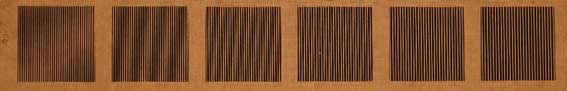
One of the characteristics of moiré is its ability to magnify tiny shapes. Magnification by moiré occurs when viewing a chain-linked fence through another, identical, chain-linked fence. The detailed fence structure is visible even at a certain distance. Figure 1 depicts a similar situation created when one set of parallel, vertical lines is superimposed on another set of parallel, vertical lines.
The size of the created moiré pattern depends on the angle between the two superimposed patterns. Figure 2 shows a moiré effect created by the sun shining through the double-layered fabric back of an office chair. The light and dark bands, apparently projected upon the lines underneath, appear as if black lines are side by side in some areas and cover each other in other areas, thereby producing a light band.
Screen printing presents numerous opportunities in which regular grids are superimposed. A regular grid can be a halftone-dot pattern or a set of parallel lines. Other possibilities include:
• The fabric, commonly polyester, stretched to a certain tension level on a frame.
• The image can be, among other things, a single halftone pattern. This (AM) pattern is supposed to be a regular pattern. Another image may consist of multiple halftones with the colors positioned at different angles.
• Last, but not least: the substrate. The substrate is not necessarily smooth, but it can be a textured pattern or even a textile.
Interference between grid patterns can cause different forms of moiré:
• Primary moiré is image interference between two or more halftone patterns at different angles. They clash during printing, because the respective angles create an undesirable wavy interference pattern.
• Secondary moiré occurs when halftone angles or line counts (rulings) clash with the weave of the fabric. Careful mesh selection can help minimize the effects of secondary moiré.
• Tertiary moiré occurs when a halftone is printed onto a texture, such as textile. The texture pattern clashes with the halftone dots.
• Local moiré only occurs in certain tonal value areas of the image, whereas primary, secondary, and tertiary moiré predominantly occur throughout the complete image.
Secondary moiré, in particular, presents the greatest challenges to screen printers. Let’s discuss the major causes in hopes of developing a better understanding of the moiré phenomenon.
Fabric selection
Fabric selection always depends on the printed image’s requirements. In general, a finer fabric allows us to print finer halftones. A rule of thumb is that the fabric mesh count is F (= 3 to 5) times finer than the halftone screen. The ration between the fabric mesh count and halftone screen ruling should not be an integer, allowing a decrease of the moiré pattern frequency to make moiré less visible.
Mesh count (lines/in.) = F x Halftone screen ruling (lines/in.)
Fabric-selection tables show us the thread grades S, M, T, and HD. Grade HD refers to a robust and strong thread for heavy-duty print jobs. A large-diameter thread superimposes more halftone dots than a thin thread and, therefore, causes more moiré, as shown in Figure 3. Furthermore, large-diameter HD threads impede ink flow significantly more than the thinner S threads. This regular restraint of ink flow is visible as moiré.
Stretching mesh to its optimum level is an underestimated and often overlooked activity. Inaccurately stretched mesh may create local moiré patterns. Locally, the ratio between the mesh and the halftone ruling differ and are no longer optimum.
Dyed fabric, as opposed to white mesh, reduces undercutting effects substantially during exposure. This, in turn, reduces loss of the tonal range, which reduces the risk of moiré.
We can approximate the risk of the appearance of moiré before the preparation of the stencil. Put the frame with the tensioned mesh on a light table and put the right side of the film positive on the print side of the mesh. Any visible moiré can be reduced by rotating the film positive across the fabric. Mark the new position and expose the image after applying the emulsion.
Dot shape
Screen printing halftones causes dot gain. The amount of dot gain is equally distributed along the circumference of the dot. This phenomenon is visible when the dots just start to touch each other. The so-called double-symmetry dot gain may cause a large jump in tonal value and may be visible as moiré. A relatively high ink deposit reinforces this effect. Moiré is reduced by choosing a dot shape that differs from the square shape of the mesh openings. Round dots or elliptical dots can resolve the issue. The advantage of an elliptical dot shape is that, due to the different distance to the surrounding dots, it produces an area with a tonal-value increase without a sudden, unwanted tonal jump. Another solution is to use different dot sizes in different tonal areas to avoid the tonal jump.
Dot size
Screen printing halftones within a tonal range of 15-85% is generally feasible. However, the requirement is that the smallest printable negative dot must be larger than the sum of one mesh opening plus two thread diameters. After all, the stencil requires sufficient support to adhere to the mesh.
On the other hand, the finest positive halftone dots are printable when the dots are above a mesh opening. Halftone dots do not appear on the substrate when the dots are superimposed on single threads or crossing mesh threads. This kind of moiré, caused by regularly leaving out dots, is strongest between tonal values of 40-60%.
Halftone screen angle
If we want to avoid primary moiré, the angle between two halftones must be 15° or a multiple thereof. In theory, we can print four colors at 0°, 15°, 30°, 45°, 60°, etc. Obviously, we should check the film positives for the appearance of film-to-film moiré. The screen used in the screen-printing process requires a compromise on the printer’s part to the eventual moiré effect caused by the four colors and the mesh fabric.
Yellow, the least visible color, is basically placed at the most visible angle, 0° or 90°. Next, a combination of theory and experience establishes the following sets of halftone screen angles depicted in Figure 4. To avoid printing halftones parallel to the threads and, as a result, the creation of harmful moiré, consider the practice of offsetting the screen angles. The screen angles represented in sets 2, 3, and 4 in Figure 4 are also suitable for single halftones, duotones, and more.
Stencil
A thick stencil can cause moiré when printing a four-color-process graphic—especially in the dark tones, where excessive build-up of several ink deposits causes irregular relief and, as a result, deformation of the dot shape. This deformation is visible as a moiré pattern. A minimum, but sufficient, emulsion over mesh (EOM) thickness prevents many issues. A thin and smooth stencil results in good contact between stencil and substrate and, therefore, produces a crisp printed dot.
Substrate
Substrates designed with surface textured can increase the chances of creating harmful moiré patterns—woven textiles, for example. We can predict and minimize the occurrence of moiré by mounting sets of film positives to the substrate. Rotating the film positives to the left or right side will reveal the problematic areas. Using the optimum angle between film positive and substrate reduces moiré between the print image and substrate.
Helpful moiré
Moiré is not necessarily supposed to be our enemy. The effect can also be helpful in identifying materials. Collect all sorts of mesh fabrics, cut samples no larger than 4 x 4 in., and mark the samples accordingly. To identify an unknown fabric, we simply put the standard sample on the unknown mesh fabric. A typical moiré pattern will form when we rotate the standard sample onto the fabric. The moiré pattern is characteristic for the two matching regular structures.
Wim Zoomer (wimzoomer@planet.nl) is owner of Nijmegen, Netherlands-based Technical Language, a consulting and communication business that focuses on flatbed and reel-to-reel rotary screen printing and other printing processes. He has written numerous articles for international screen-printing, art, and glass-processing magazines and is frequently called on to translate technical documents, manuals, books, advertisements, and other materials. He is also the author of the book, “Printing Flat Glass,” as well as several case studies that appear online. He holds a degree in chemical engineering. You can visit his Website at www.technicallanguage.eu.


Subscribe

Magazine
Get the most important news
and business ideas from Screenprinting Magazine.
Most Popular
-

 Art, Ad, or Alchemy1 month ago
F&I Printing Is Everywhere!
-

 Case Studies1 month ago
High-Density Inks Help Specialty Printing Take Center Stage
-
 Andy MacDougall1 month ago
Functional and Industrial Printing is EVERYWHERE!
-

 Columns2 weeks ago
8 Marketing Mistakes Not to Make When Promoting Your Screen Printing Services Online
-

 Editor's Note2 weeks ago
Livin’ the High Life
-

 Thomas Trimingham2 months ago
“Magic” Marketing for Screen Printing Shops
-

 Marshall Atkinson2 weeks ago
How to Create a Winning Culture in Your Screen-Printing Business
-

 News & Trends1 month ago
What Are ZALPHAS and How Can You Serve Them in Your Print Business?