Industrial applications present screen printers with some of the most unusual requirements they’re likely to face. Odd surface shapes, sizes, textures, and substrate compositions are just a few of the dozens of special considerations that challenge screen shops. But the screen-printing process can accommodate these requirements, which has made it a premier imaging method for industrial applications and a profitable venture for shops brave enough to take on such jobs.
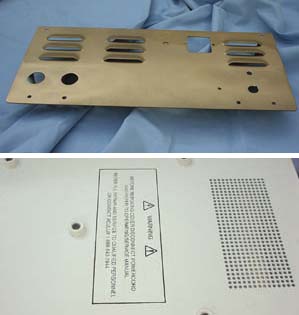
Among the most difficult industrial applications are those involving control panels and boxes–not nameplates, oven fronts, or membrane switches mass-produced for consumers, but plain metal machinery enclosures, control panels, and other heavy-duty industrial components. These items are meant to be more functional than attractive, and the graphics they feature tend to be simple one- and two-color logos and instructions. Nearly all of these products are made of powder-coated metal with a glossy or matte finish. But what really makes some of them unusual and challenging for screen printers is that they have studs, inserts, louvers, tabs, and bolt heads sticking out of their surfaces where the graphics are supposed to be printed (Figure 1).
When confronted with protrusions on industrial items, screen shops have three main decorating options: direct pad printing, decorating with printed decals, or direct screen printing. Other options, such as direct inkjet printing, computer-controlled syringe imaging, etching, and routing, may also be considered. But for industrial parts with challenging surfaces, they’re the most inferior alternatives.
Pad printing
When a screen shop faces these types of irregular surfaces, the initial reaction is invariably to use pad printing. In most cases, however, pad printing is a poor solution. The process is well suited for curved surfaces, but the industrial products in this class have flat surfaces with things poking out of them. So conforming to a curved surface is a non-issue. Furthermore, the printed areas on these parts are usually much larger than what conventional pad presses support, while the print quantities are much smaller than in typical pad applications. Also, the powder coating often found on these items is notoriously difficult to print with available pad-printing inks.
Advertisement
Pad-replacement costs are another issue. Pads tend to fall apart if you print over sharp objects like tabs, studs, and bolt-heads. And unlike screens, which can be saved and reused almost indefinitely for repeat jobs, pads have a limited shelf life of about 12 months. So, while pad printing is great for smooth, concave or convex surfaces, in general, the process is inadequate for the industrial applications discussed here.
Decals
While they’re not an ideal solution, decals are often selected for lack of better alternatives. To accommodate projections, the graphics are created either as single decals with several die-cut holes through which the projections can pass or as multiple smaller decals for placement between the projections.
Screen printing, diecutting, and applying high-quality decals for these low-volume applications is rather costly. You could create the decals using digital printing and cutting equipment, but the cost may still be high, and you would sacrifice the quality, durability, and appeal of direct-screen-printed graphics.
Regulatory problems also enter the picture because decals stuck on control boxes and equipment are often required to be non-removable. If this is the case, a regulatory agency may require you to put rivets through the decal no matter how many times you swear that the adhesive you used is as permanent as they come. Direct-printed labels and designs, on the other hand, are automatically considered non-removable, whether or not they are.
Screen printing
Advertisement
Screen printing, as it’s generally practiced, may seem unsuitable for these jobs because surface projections can poke holes in screens. And even if the surface projections are not sharp, getting the stencil close to the printed surface requires either loose screens or screens that are stretched beyond their optimal performance levels. The question is, how do you get around these limitations?
Making the screens suitable for the substrate is the trick to printing on these products. And the way you do this is by putting holes in the screens that allow the projections to protrude so that the screen and substrate can make contact during printing. While modifying screens in this way will limit the printing to manual production (as will the three-dimensional nature and varying sizes of the products), this is unlikely to pose a problem since print quantities for such parts are usually less than 1000 and often fall below 100.
Printing equipment As mentioned earlier, a manual press is required for decorating these products. The primary requirements for such a printing system are listed in order of importance below:
1. The ability to ensure accurate registration
2. A screen-holding device that keeps the screen in horizontal position at all times (clam-shell presses are very awkward for this purpose)
3. A mechanism that facilitates raising or lowering the screen (or table) for accurate off-contact
Advertisement
4. A printing table that can accept various jigs and attachments for holding three-dimensional parts in place
In most shops, presses used for these applications are custom built.
Squeegees Many of these products require one or more short squeegees that fit within a printing window. The squeegees should have a comfortable handle, medium durometer, and sharp edges. If a soft-durometer squeegee is needed (e.g., for printing on wrinkle-finished surfaces), a stiffened back plate should be used to prevent the blade from bending too much.
Tooling Printing on these unique products requires some tool-making capabilities, including cutting, drilling, and tapping aluminum. All other production requirements for this type of printing are the same as those encountered when screen printing other products. You need well-prepared artwork, well-made screens of the appropriate type, properly mixed inks, and good setup procedures that are quick and easy to duplicate.
Screen design The entire screen assembly for decorating industrial parts with projections consists of a frame, a sub-plate made from of 0.125-in. (3-mm) aluminum sheet metal, and the screen mesh. The screen frame may be any type of aluminum frame, including retensionable varieties. The sub-plate’s purpose is to hold mesh in place over the printing area and allow the removal of mesh over projections. The sub-plate has cutaway openings that provide relief for the projections on the parts and a printing window where the image falls (Figures 2A and 2A). Standard screen adhesive secures the screen mesh to the entire surface of the sub-plate.
You can produce the screen assembly in two ways. The first, and simplest, way is to make the sub-plate, complete with openings and windows, the same size as the inner dimensions of your frame and then glue the sub-plate to the tensioned screen mesh on the inside (squeegee side). The second way is to make the sub-plate the size of the outer dimensions of the frame and then screw it to pre-tapped holes in the frame. In the second method, you would have to glue the tensioned mesh to the sub-plate after the sub-plate is attached to the frame.
Which method is better? That depends on how large your screen is and how straight (flat) the sub-plate is. The first method allows the use of roller frames and is a lot easier to perform if the sub-plate is flat and the screen area is less than 100-120 sq in. (650-775 sq cm). But if the sub-plate rocks on a flat surface, or if the screen area is much larger, then the second method is better. Just keep in mind that the second method limits your choice of frames to square-tube varieties.
The openings in the sub-plate have certain minimum requirements to en-sure printability (Figure 3). The clearance between the projections and the sub-plate holes surrounding them should be no less than 0.062 in. (1.5 mm), which would allow for a registration adjustment of ± 0.062 in. The minimum distance between the edge of the printing window in the sub-plate and the image must be no less than 0.250 in. (6.5 mm) wide (squeegee length) and 2.0 in. (50 mm) long (squeegee-stroke direction). The edge of the printing window should not be closer than 0.187 in. (4.75 mm) to any of the projections. These dimensions can and should be larger if allowed by the projections and the image. The inkwell (the 2-in. dimension) can be smaller, but the smaller it is, the more difficult it will be for the printer to control the ink.
Your customer should be made aware that, based on these parameters, all images should be spaced at least 0.437 in. (11.1 mm) from any projections on the surface. You could apply additional tweaks and tricks to reduce some of these dimensions and print closer to the projections, but these additional steps are cumbersome and time consuming from a production standpoint. If you have to compromise on these dimensions, you should be able to charge extra for such additional services.
The overall size of your screen assembly determines the overall size and location of the image. If the image on a large panel is only one small “warning” symbol, then a relatively small screen can be used. On the other hand, if several images appear all over the part, then making one large screen is more reasonable than making several small ones–at the very least, this approach reduces your setup time.
Imaging and art requirements Once you have the screen assembly made, you can process it in the usual way. Using capillary films to produce the stencils is more practical than using direct emulsions. You can save a lot of material this way because you only need the stencil over the image areas, and you will also have better control over the stencil thickness, which can help produce a sharper image.
Because you have less than ± 0.062 in. of tolerance for registration (the area in which you can move your screen around the projections), you must place the artwork precisely in position on the screen. To do this, you must show the location of the relief holes on the artwork so the screenmaker can place the image accurately over the holes in the sub-plate. Before each screen is produced, a decision has to be made about each of the following concerns:
* how to hold the part
* where to place the part on the printing machine
* how the artwork has to be prepared for the screenmaker
* how far the image has to be from the screen-holding clamps
* what is the maximum allowable ink-well for ease of printing
After addressing these considerations, you can determine the size of the screen assembly, produce the assembly, and provide instructions to the artist and screenmaker.
Printing Using the right squeegee length is essential when printing with your special screen assembly. The length must be greater than the width of the printed image but smaller in size than the printing window in the sub-plate. For example, if the image is 3 in. (76 mm) wide and the relief hole is 4 in. (101 mm) wide, then the squeegee should be 3.5 in. (88 mm) long.
When printing in small, restricted areas, the off-contact must be kept as small as possible. Depending on image size, off-contact should be no more than 0.020-0.040 in. (0.5-1.0 mm). When the image is very close to the edge of the printing window, the screen will not flex enough to reach the part across a great off-contact distance. The screen fabric will either break or come loose from the screen assembly. If the screen happens to stick to the substrate during printing because of the low off-contact, it is better to change the properties of the ink than to try to increase the off-contact distance.
As previously mentioned, the ideal printing machine for this process should hold the screen in a horizontal position at all times. On a clamshell machine, the ink is going to run all over the screen and may flow through the relief holes onto the part. But if the projections on the part are 0.5 in. all (12.5 mm) or less, the relief holes can be covered prior to printing. If the image is far enough from the projections, covering the holes should not be necessary. Without a cover, however, you always face a chance that the ink will drip on the part through the hole. A cover can be made from flexible packaging tapes or, if the projections are too tall for plain tapes, from glued down latex membrane. If the projections are taller than 0.5 in. and very close to the image area, you will need to make special caps that fit over the holes to keep the part clean.
Old faithful
Screen printing has always been the most direct and simplest form of imaging on unusual surfaces requiring unique inks. At one time or another, printing on golf balls, dinner plates, tumblers, and dozens of industrial products was only possible with screen printing. Today, a number of other imaging processes can do just as well or better. Fortunately, as the products in this article demonstrate, designers and engineers keep coming up with new and unusual applications that will keep screen printers busy as long as they have the courage to tackle these products in an innovative way.


 Art, Ad, or Alchemy2 months ago
 Case Studies1 month ago
 Andy MacDougall2 months ago
 Columns2 weeks ago

 Marshall Atkinson2 weeks ago
 Thomas Trimingham2 months ago
 News & Trends1 month ago