Screen Printing EL Lamps for Membrane Switches
Published
24 years agoon
Low-temperature light emission, also known as luminescence, has always surrounded us in the natural world. You may have seen it in the form of an eerie glow emanating from bacterial life in a marsh or recall it in the blinking radiance of lightning bugs you chased as a child. But controllable luminescence is a much more recent invention. One of the first examples of artificially produced luminescence occurred in Paris in 1936, when George Destriau, working in Madam Curie’s laboratory, discovered that a zinc sulfide compound emitted light in the presence of an electric field.
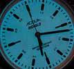
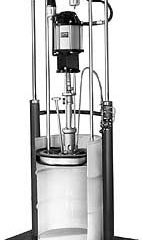
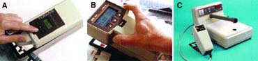
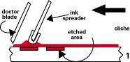
Low-temperature light emission, also known as luminescence, has always surrounded us in the natural world. You may have seen it in the form of an eerie glow emanating from bacterial life in a marsh or recall it in the blinking radiance of lightning bugs you chased as a child. But controllable luminescence is a much more recent invention. One of the first examples of artificially produced luminescence occurred in Paris in 1936, when George Destriau, working in Madam Curie’s laboratory, discovered that a zinc sulfide compound emitted light in the presence of an electric field. Essentially, he had discovered the first synthetic electroluminescent (EL) phosphor. Later, during World War II, a considerable amount of research was carried out on phosphors of various types, mainly destined for radar screens, the precursors to modern television tubes. And during the late ’40s and early ’50s, transparent conductive coatings were created for military applications, such as de-icing systems for aircraft windshields. These coating developments played a key part in another "display" technology–liquid crystal displays (LCDs). Each of the previous advances brought us one step closer to today’s EL lamp technology, which really saw development beginning in the 1950s, when various coatings, including a phosphor, were fired onto heavy steel plates to create ceramic EL lamps. When a current was passed through the base plate, the device emitted light. Today, this technology has given way to thin, film-based EL lamps that are ideal for small-area backlighting requirements common on many electronic devices, including those with membrane-switch controls. How do EL lamps work? An EL lamp is a lossey parallel-plate capacitor. In other words, it’s an electronic device that is electrically charged, then loses its energy in the form of light. To do this, an EL lamp requires an AC current, which is applied to both plates. The current allows energy to build up within a phosphor layer between the plates, and the energy is released as light during each half cycle of the AC current (when the electrical field or charges applied to the plates alternate). The number of times that the field changes within a given time period (the frequency of the current) influences the brightness of the light emitted by the phosphor. How much light can you expect an EL lamp to generate? To put this question into perspective, consider a typical watch face with an EL light source. When illuminated, such watch faces typically produce around 1 footlambert (3.5 candela/sq m) of light, which is more than adequate to read the information on an LCD or analog watch (Figure 1). For most membrane-switch applications, light delivered through the graphic overlay at 3-5 footlamberts (10-17 candela/sq m) is considered ideal. But the intensity of the light emitted by an EL lamp can drop by as much as 50-80% as it passes through a graphic overlay. Therefore, the light emitted by the lamp must be at least twice as intense as you want at the surface of the overlay. Achieving such intensity levels, however, is not a great challenge; most EL lamps in devices with membrane-switch controls deliver 7-10 footlamberts (24-34 candela/sq m). Production options Today, you have three options for incorporating EL lamps into a membrane-switch assembly: buying premanufactured lamps, printing your own lamps over a specially coated polyester film, or printing all components (layers) of the lamp onto standard films used in membrane-switch production (polyester, polycarbonate, etc.). All these options result in a high flexible EL lamp (Figure 2). Using premanufactured EL lamps You can purchase premanufactured EL lamps of very good quality from a number of commercial sources. But because the lamps must be custom designed for your particular applications, the cost may be prohibitive. The more complex the membrane switch, the greater the expense of outsourcing lamp design and production. In some cases, the physical characteristics of commercial lamps, such as thickness, may also preclude them from particular switch applications. All the materials required to manufacture a complete EL lamp are available commercially. So if a premanufactured EL lamp proves too costly or can’t match the space requirements of your particular switch design, your next option is to produce your own EL lamps. Printing EL lamps on coated polyester The most common approach to in-house EL lamp production is to purchase polyester film that has been sputter-coated with indium tin oxide (ITO), a transparent conductive material that serves as the lamp’s outer electrode (one of the two parallel "plates" described earlier). Over the ITO-coated sided of this polyester, you print a bus bar (generally silver) to ensure maximum current to the coating. Next, you print a light-emitting phosphor layer, followed by a dielectric insulating layer of barium titanate. You complete the lamp with a final layer of silver or conductive carbon ink, which serves as the second electrode. This layer configuration is illustrated in Figure 3. You can laminate an additional layer of adhesive-backed polyester or a similar film over the second electrode to encapsulate the lamp and provide additional electrical and environmental protection. However, most membrane switches are, by nature, sealed devices. Generally, EL lamps will be protected between the standard films that comprise the entire switch/graphic-overlay assembly. The primary drawback to using ITO-sputtered polyester for EL lamps is that it restricts you to a specific construction method. With ITO-sputtered polyester, the print sequence always begins with the bus bar over the ITO coating, followed by the phosphor, the dielectric insulating layer, and finally, the rear electrode. Consequently, the completed lamp always emits its light through the polyester film. For some applications, the extra layer of polyester can be an unwarranted expense and can reduce design flexibility. Printing the entire EL lamp For applications in which ITO-sputtered polyester is undesirable, new ITO inks may be the answer. These inks provide conductive properties similar to coated polyester, but because they can be printed, they offer greater design latitude. Recall that when producing lamps with ITO-sputtered polyester film, the print sequence always results in the light-giving side of the lamp facing through the polyester. With printable ITO, you can print the sequence of layers in reverse order. This means you can print the complete lamp on the outer face of the switch’s last (top) film layer or on any polyester or polycarbonate layer where it can illuminate legends or other items on the graphic overlay. General production pointers Whether you use ITO-sputtered polyester as the base for your EL lamp and print each additional layer, or produce the entire lamp from printable materials, you need to keep several processing and design considerations in mind. Here are a few of the most important: Keep the production environment clean When printing EL lamp layers, cleanliness is of paramount importance. If you’re like most switch producers, you already maintain high standards of cleanliness to ensure quality graphics and circuit printing. For EL lamp production, you don’t need a Class 10,000 clean-room environment, just good precautions to ensure that the inks won’t be contaminated by dust, moisture, etc. Use polyester mesh As a general guideline, use monofilament polyester screens for printing each layer of the lamp. You may be tempted to use stainless steel to resolve fine elements of the lamp, such as leads or traces, but I recommend against it. The problem is that when printing the phosphor and barium titanate layers, the contents of the inks are abrasive to metal and will leave a stainless steel screen highly polished. You’ll then be left to wonder where the metal particles have gone–not the kind of concern you want raised when you’re printing materials that are supposed to have insulative characteristics. Carefully monitor cured ink film thicknesses The cured thickness of each printed layer is critical to lamp performance and must be accurately maintained. To verify the thickness of cured layers, I recommend that you use a digital micrometer, both in the product development stage and during production. Printing an EL Lamp.. The following recommendations are based on producing EL lamps with light-giving areas up to 2 x 2 in. Keyboard keyheads tend to be much smaller than this and can be supported with smaller EL lamp areas (Figure 4). Creating small lamp areas is especially practical if you’re printing all the layers (including the ITO), because selective area lighting reduces ink consumption as well as the total power required to operate the completed lamp. For simplicity’s sake, assume that the EL lamp in the following example will be printed second surface on either a standard film or on ITO-sputtered polyester. Bus bar The first element you need to print on the film is the front bus bar, usually consisting of silver ink. To print bus bars, which typically measure less than 1 mm wide, use a 305-355 thread/in. polyester screen. After printing, cure the ink at 220°F (105°C) for approximately 10 min. The cured bus bar should be approximately 8 microns thick. If you’re working with ITO-sputtered polyester, the bus bar will be printed on the ITO-coated sided of the film, as shown in Figure 3. If you’re working with printable ITO, you’ll print the bus bar directly on a clear standard film before printing the ITO layer (switching the bus bar and ITO layers shown in Figure 3). The bus bar needs to surround the area to be lit and should be tracked out to a suitable contact point beyond the edge of the lamp assembly. Whether you’re printing the bus bar on ITO-sputtered polyester or following the bus bar with a printable ITO coating, the ITO layer should slightly overlap the bus bar’s entire width. ITO For lamps produced entirely from printable components, the next layer to print will be the ITO coating itself. Meshes ranging from 305-355 thread/in. are suitable for ITO printing, as are the curing parameters that were specified previously for the bus bar. The cured ITO layer should be approximately 10 microns thick after curing. Remember, this layer should overlap the bus bar’s entire width to ensure good electrical contact. Phosphor From this point on, all the processing requirements are identical, regardless of whether you’re using an ITO-sputtered polyester or printable ITO. In both cases, the next layer down will be the phosphor. But before we discuss printing procedures for this layer, let’s look at the characteristics of phosphor inks. The life and light-emitting capabilities of phosphors are reduced by exposure to water, so today’s printable phosphor formulations feature phosphor particles that are encapsulated in silica to repel moisture. The presence of the silica does not prevent the phosphors from generating light when exposed to the electric field generated by the lamp’s electrodes. Depending on the chemistry chosen, phosphors will emit light in one of a narrow range of colors, either green, blue, or yellow (Figure 5). These three chemistries can be blended to produce an effective white light as well. Additionally, red fluoro dyes can be added to phosphor blends that produce a green/blue light to provide a white light emission. To ensure a uniform lighting effect, the printed phosphor layer must be smooth and consistent, and the phosphor particles it contains must be evenly dispersed. I recommend printing the phosphor layer twice, wet on wet, using a 280 thread/in. screen, which will provide a cured ink thickness of about 38 microns. Alternately, you can double print with a 230 thread/in. mesh, which will provide a cured ink-film thickness of approximately 42 microns. The phosphor layer should extend past the edge of the bus bar profile by 0.5 mm and should also be cured at 220°F for 10 min. If the cured phosphor layer falls below 25-30 microns, the result will be dull, grainy illumination when the lamp is operated. And if the phosphor layer is greater than 50 microns thick, it not only wastes ink, but effectively pushes the conductive plates further apart. This results in lower energy conversion within the phosphor and, in turn, lowers the overall light output of the lamp. The consistency of the cured phosphor layer can be easily checked with an ultra violet "black light." Under this light source, any print faults, such as lines and striations, will be readily visible to the naked eye. Dielectric insulator The next layer to print will be the barium titanate dielectric insulating layer, which also requires careful attention during printing and curing. The thickness of this layer can vary to match insulation requirements for the particular power level under which the completed lamp will operate. Typically, it’s printed in two passes (with drying between each pass) using a 110-140 thread/in. screen to provide a cured thickness of 10-15 microns. Double printing reduces the risk of pinholes and other voids in the layer, which could lead to shorts in the lamp. To cure this layer, I recommend using a ramped curing profile that starts at 120°F (50°C) and gradually increases to 220°F. The ink should then remain at 220°F for 10 min. to ensure a complete cure. The slow temperature build up will allow solvent gases or air bubbles to escape before the ink "skins" over, thereby helping you avoid the pinholes mentioned previously. The second print should leave the surface looking very smooth with no imperfections. It may be necessary to print a thicker dielectric if the lamp is to experience higher than average voltages. In such situations, you can print two passes with a 110 thread/in. screen, or alternately, three passes with a 140 thread/in. mesh. The insulating layer must overlap the bus bar profile and should extend beyond the edges of the preceding phosphor layer. This ensures good electrical protection by preventing the silver ink or ITO from side tracking or migrating from the front to rear electrode. Rear electrode The rear electrode should be printed to match the inner edge profile of the front bus bar. Remember, the phosphor is excited within the active field between the two electrodes, so matching the electrode sizes as suggested no only helps avoid ink waste, but also produces an EL lamp that is more aesthetically appealing because it limits light emission to desired areas. For producing the rear electrode, you can choose between a carbon or silver ink. If using carbon inks, you will also need to print a silver trace over the carbon that resembles the bus bar used on the front ITO electrode. Additionally, you need to track out the rear electrode with a silver trace beyond the lamp area. This trace needs to match the position of the trace on the front electrode. Note that if you track out the rear electrode with a carbon trace, the highly-resistive carbon may heat up during operation and cause lamp failure. Also, the black color of carbon inks tends to reduce back scattering and reflection of light within the lamp, which in turn reduces the intensity of light emitted from the lamp’s front face. However, carbon ink offers significant cost savings over silver ink, which makes it attractive if customer specifications permit. Powering the lamp The final issue to consider in EL lamp design and production is the overall portability of the lamps. In most cases, when membrane keypads are part of hand held or portable equipment, the devices are battery powered. So if the switch includes an EL lamp, an inverter is required to convert the DC current from the batteries into the AC current required to drive the lamp. In the past, inverters were large compared to other switch components, which restricted the use of EL lamps in smaller devices. However, today’s inverter technology matches the simplicity, portability, and cost economy of EL lamps. Small, surface-mounted inverters, including integrated chips, are now common in cell phones and watches and are rapidly spreading to broad range of portable devices with membrane-switch controls. Note that in modern inverters, AC voltage and frequency has been shifted from the traditional 115 v/ 400 Hz levels that were the standard when EL lamps were first developed for aircraft cockpit lighting, to lower voltages of 60-70 v and frequencies of 1000-1500 Hz. The lower voltage and higher frequency tend to color-shift green phosphors more into the blue region and shorten phosphor life. However, today’s encapsulated phosphors are more than sufficient to cover the life-expectancy of the portable products in which they are used. Conclusion EL lamp technology not only can add to the aesthetic quality of your membrane-switch products, but also can make them safer and easier to use–especially on devices that will be operated in low-light conditions. And considering the recent advances in electronic components and ink systems, as well as the ability to buy premanufactured lamps or produce them yourself, incorporating EL lamps in your products is easier than ever. About the author Born in Birmingham, England, Ken Burrows specialist in conductive coating and electroluminscent technologies. His background includes work in the aviation industry, where he developed a patented ITO sputtering process for aircraft windscreens and EL lighting systems for cockpit instruments. After moving to the US in 1995, he developed the concept of an ink kit for printing EL lamps onto various substrates. His firm, EL Specialists, Inc., Allen, TX, is presently working with Acheson Colloids, Co., Ontario, CA, on new printable EL lamp applications.
SPONSORED VIDEO
Let’s Talk About It
Creating a More Diverse and Inclusive Screen Printing Industry
LET’S TALK About It: Part 3 discusses how four screen printers have employed people with disabilities, why you should consider doing the same, the resources that are available, and more. Watch the live webinar, held August 16, moderated by Adrienne Palmer, editor-in-chief, Screen Printing magazine, with panelists Ali Banholzer, Amber Massey, Ryan Moor, and Jed Seifert. The multi-part series is hosted exclusively by ROQ.US and U.N.I.T.E Together. Let’s Talk About It: Part 1 focused on Black, female screen printers and can be watched here; Part 2 focused on the LGBTQ+ community and can be watched here.
You may like


Advertisement

The Profit Impact of a Market Dominating Position

Inkcups Announces New CEO and Leadership Restructure

Hope Harbor to Receive Donation from BlueCotton’s 2024 Mary Ruth King Award Recipient

Advertisement
Subscribe

Bulletins
Get the most important news and business ideas from Screen Printing magazine's news bulletin.
Advertisement
Most Popular
-

 Case Studies2 months ago
High-Density Inks Help Specialty Printing Take Center Stage
-

 Art, Ad, or Alchemy2 months ago
F&I Printing Is Everywhere!
-
 Andy MacDougall2 months ago
Functional and Industrial Printing is EVERYWHERE!
-

 Columns3 weeks ago
8 Marketing Mistakes Not to Make When Promoting Your Screen Printing Services Online
-

 Editor's Note2 weeks ago
Livin’ the High Life
-

 Marshall Atkinson2 weeks ago
How to Create a Winning Culture in Your Screen-Printing Business
-

 Thomas Trimingham2 months ago
“Magic” Marketing for Screen Printing Shops
-

 News & Trends2 months ago
What Are ZALPHAS and How Can You Serve Them in Your Print Business?