Prepress & Screen Making
Published
21 years agoon
The screen-printing industry is full of fascinating production recommendations and procedures that are based on common practice. But when we examine them closely, many accepted methods turn out to be entirely false or seriously flawed.
The screen-printing industry is full of fascinating production recommendations and procedures that are based on common practice. But when we examine them closely, many accepted methods turn out to be entirely false or seriously flawed.
One of the production issues that areas containing the most misinformation has to do with halftone line count-to-mesh-count ratios. There are all sorts of ideas floating around out there. The two most common ratios I hear recommended to printers are to use either 3.5 or 4 times the mesh count to the halftone line count. This month’s column will explore in depth the various components and how they interplay. By the time I am finished, you’ll understand that precise prediction of ratios is impossible.
To begin, let’s establish the basic scenario. Assume we have a specific halftone frequency that we would like to work with–say 65 lines/in. Using the most common recommendations and rounding to the nearest common mesh count, the suggested meshes to use for line count would either be 230 threads/in. (227.5) at a ratio of 3.5 times the line count or 255-265 threads/in. (260) using the ratio of 4 times the line count. These would be the minimum mesh count values to use. Higher thread counts would further reduce the possibility of moiré, but here we’ll just focus on the recommendations.
Halftone line count
Now let’s turn our attention to the halftone line count. We must consider two essential factors when it comes to line count: the real area the dot is covering and the effect of angling on the actual frequency of halftone dots.
The basic line count is really not a very good indicator of what is happening in the image. When we speak of a halftone at 65 lines/in., we are really referring to the frequency ruling. In the early days of glass halftone screens, glass was scribed with parallel lines. These lines were filled with a black or gray dye. Two sheets of glass were glued together with the lines perpendicular to each other. This created a grid of lines and square spaces that was used to generate the halftone dot on the film during exposure. The frequency of the grid was only partially responsible for determining how much area the dot actually covered. With a short exposure, a very small dot was formed in the center of each grid opening. As the exposure increased, the dot grew in size until it finally connected to adjoining dots, forming a checkerboard at the 50% tonal size. This is typical of a square-dot halftone structure.
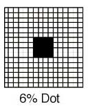
Moving to today’s digital prepress model, halftones no longer are formed using glass or contact screens and varied exposure levels, but rather by depositing or exposing a matrix of pixels using a digital imagesetting device. Each halftone dot in the digital model is called a cell and is typically made of 255 pixels that can be turned on or off. Figure 1 shows a halftone cell that represents one halftone dot of a 6% tone. It’s clear that the area covered by the dot is much smaller than the cell, which is where the problems begin for screen printers. The actual area covered by halftone dots varies by percentage, with 50% representing the largest area of coverage. The actual area of the halftone is mirrored on either side of this 50% value. For instance, a 40% dot has the same area of coverage as a 60% dot. The former represents a positive dot area and the latter a negative area.
The problem with dot area becomes more complicated when we rotate the halftone (change its angle). Rotating the angle dramatically changes the actual area covered by each dot. Figure 2 illustrates two different types of dots: square and elliptical. While both represent the same dot area, the orientation of the dots will clearly influence the potential for mesh interference.
Halftone orientation affects how many dots we can stack in a given area. When the dots are oriented at 90°, a vertical stack, the frequency is the stated value. At 65 lines/in., we would stack 65 vertical dots. As the angle is rotated, however, the shape and orientation of the dots also changes, reaching the maximum amount of change at 45°. In order to maintain the same frequency of 65 line/in. at this angle, the actual dot would have to be equivalent to a 74 line/in. dot at 90°. In other words, the dot’s size would have to be reduced by 70.72% to fit at 65 lines/in.
In reality, when a 65-line/in. halftone is rotated 45°, the result is the equivalent of a 46 line/in. stack, which represents an increase in the diagonal of 141% over the original dot size. For printers, it’s important to realize that the real, effective frequency is different for each angle in the halftone sequence. This frequency change is what causes the familiar rosette that forms when process-color halftones are correctly printed in relation to each other.
Mesh count
Now, let’s move on to the mesh count itself. This is another item that is very elusive and constantly changing. Our first point of consideration is the accuracy of the thread count. You should understand from the start that all mesh is woven to metric standards, and the values we see are converted to English and rounded to the nearest five threads/ in. For example, our 305-threads/in. mesh is really 120 threads/cm. The conversion to English is 2.54 x 120 = 304.8, which means our approximation is pretty accurate. Some mesh counts aren’t reported so accurately, such as our 390 threads/in. mesh, which is really 155 threads/cm and converts to 393.7, a figure that is then rounded down.
Of course, the stated thread counts will vary differently in the warp and weft directions. The warp direction of the mesh is controlled by the beam during weaving and is generally accurate. It may vary by just a few threads per inch. The weft direction (side-to-side) is more variable. The count in this direction is controlled by the looming process as the thread moves back and forth. Depending on the manufacturer, there may as much as ;5-7% variation from the stated thread count due to weaving. This is a big number–in the worst case, it would mean that a 390-threads/in. mesh could come in anywhere between 365 and 417 threads/in. Such fluctuations are unlikely, but it’s important to realize that the mesh count is probably not precisely what it is stated to be and changes over the entire bolt of mesh.
Some manufacturers will provide mesh-count values at the recommended tension level. This is ideal because it represents the real threads per inch we’ll get when we use the mesh in production. Unfortunately, most manufacturers will provide mesh count in the relaxed state. This is troublesome because degrees of elongation required to achieve printing tension varies with mesh brand and type. The lower the modulus of elongation, the less change in thread count that will occur.
As an example, with 305-threads/in. mesh, the actual thread count at a tension of 25 N/cm might only be 290 threads/in. or less. The higher the tension, the lower the actual thread count at the time of imaging. The more we stretch the mesh, the more we change the thread count. Add to this the variation in weaving, and the total magnitude of variation we face becomes apparent.
To address these issues, we can use the thread counters offered by various suppliers, which allow us to determine, to the exact thread, what the mesh count is. These measuring films are refined versions of the old mesh/halftone tests that have been around for years. The older versions usually were limited to 150 threads/in., but the new versions will go all the way up to 460 threads/in. This makes them highly effective in the modern screen-print shop. Check with major suppliers for thread counters, which are generally less than $100 and well worth the investment.
One last point while we are on the subject of mesh count: It is very important to remember that the actual tension and actual mesh count are dynamic and continually change during the course of a print run. Increasing off-contact distance and peel settings can change both values because these adjustments require us to stretch the mesh down to the print surface. If the peel or off-contact is not constant, and the screen-to-print distance changes, tensions and mesh counts will be sure to vary. This is a crucial concern for those printing halftones with UV inks because it can have a huge impact on color-to-color moiré at the print surface. The altered mesh count from stretching will change the frequencies of halftone dot, causing them to interfere with previously printed dots and creating a new source of moiré.
Too many variables
So where does this all leave us? Mostly in a state of constantly changing confusion. The range of tone and detail in the image determines the size of the halftone dots as well as the coverage area. We cannot do anything about this. The rotational angle of the dots effects frequency, and we can change this. The mesh count is all over the place, and constantly changing during the run. No help there.
The bottom line is that we can only guess at the halftone dot to mesh-count ratio. We can expect moiré at some point, and we’ll find a way to deal with it. Relying on an artificial rule of thumb is pointless and a waste of time. The only real defense we have is to be mindful of where the variables are coming from and counterattack.


Subscribe

Magazine
Get the most important news
and business ideas from Screenprinting Magazine.
Most Popular
-

 Case Studies2 months ago
High-Density Inks Help Specialty Printing Take Center Stage
-

 Art, Ad, or Alchemy2 months ago
F&I Printing Is Everywhere!
-
 Andy MacDougall2 months ago
Functional and Industrial Printing is EVERYWHERE!
-

 Columns3 weeks ago
8 Marketing Mistakes Not to Make When Promoting Your Screen Printing Services Online
-

 Editor's Note3 weeks ago
Livin’ the High Life
-

 Marshall Atkinson3 weeks ago
How to Create a Winning Culture in Your Screen-Printing Business
-

 Thomas Trimingham2 months ago
“Magic” Marketing for Screen Printing Shops
-

 News & Trends2 months ago
What Are ZALPHAS and How Can You Serve Them in Your Print Business?