Prepress & Screen Making
By Fernando Zicarelli, Dynamesh Inc.
By Fernando Zicarelli, Dynamesh Inc.
Mesh thickness and emulsion-over-mesh (EOM) level both play a critical role in metering the thickness of any coating deposited with the screen-printing process. A printer’s ability to predict the deposit thickness that a particular mesh and stencil combination will deliver depends primarily on the accuracy and reliability of mesh- and stencil-thickness measurements. Critical electronics applications, for example, require tightly controlled deposits of conductive materials to ensure that printed circuits provide the correct electrical properties (conductivity, resistivity, etc.). Without accurate mesh/stencil thickness measurements, achieving the ideal coating thickness becomes a time-consuming exercise in trial and error.
Several years ago, I began a study to compare thickness variations in stainless-steel screen fabrics produced by four different mesh manufacturers. I measured meshes with similar thread counts and thread diameters from each manufacturer, then compared my results with measurement data they provided. What emerged were significant variations in mesh thicknesses among the manufacturers and between their measurements and my own. It became apparent that a statistical-control study was necessary to determine what combination of tools and procedures would deliver the most accurate thickness measurements.
First, I had to find out what measurement tools and methods each of the mesh manufacturers was using. I was not surprised to learn that each employed a different device, a different probe diameter, and a different measuring force. While the type of measuring device used didn’t concern me, I believed that the differences in probe diameters and measuring forces could significantly alter the thickness values returned and focused my study on these two areas.
The discrepancies between the stainless-steel meshes was similar to what we, at Dynamesh, occasionally experience with customers who require us to provide mesh or precoated screens with exacting thickness tolerances. In several instances, we have provided mesh or coated screens to the specifications requested by customers, only to have the buyers report that the thicknesses did not match their specifications. Although our measurements said the thicknesses were correct, the measurement tools and techniques used by our customers were delivering different results.
While I acknowledge that it’s important for mesh manufacturers to be aware of how their customers are measuring mesh and stencil thickness, I believe it’s more important that measuring equipment and procedures for their use be calibrated and standardized for the screen-printing industry. Without universally accepted standards for measuring mesh and stencil thickness, measurement discrepancies will never end.
This article will show that thickness variations generally are caused by variables within the thickness gauges themselves. It also will compare the most common types of thickness gauges and assess their overall accuracy.
Understanding thickness gauges
Most of the thickness gauges used in the screen-printing industry are contact gauges–meaning they make physical contact with the item being measured–and all provide some form of digital readout. When using a contact gauge for screen or stencil measuring, it’s essential to have a flat, solid surface or base on which the mesh will rest during the measurement process. The base provides a firm contact point when the measuring probe is lowered onto the mesh.
Gauging force is the force that the contact probe applies to the mesh or stencil. Excessive force can deform the measuring probe’s tip and the material being measured. And if the force is too small, any lint or foreign particle on the mesh could prevent the probe from making full contact. The actual amount of gauging force to use with a thickness gauge depends on how the device deploys its contact probe during the measuring process. I have documented gauging forces ranging from 0.01-8 Newtons (N).
The deployment mechanisms found on thickness gauges fall into three categories: spring actuated, pneumatically driven, or electrically motorized. With a spring-actuated gauge, the operator depresses a lever to retract the contact probe, then places the mesh on the measuring base. With the mesh in place, the lever is released and the probe deploys to take the thickness measurement. Such gauges rely on a spring that compresses when it is retracted or extends when it is released.
The measuring force applied by spring-driven gauges can vary depending on how much the spring is extended or retracted. In theory, if too much force is applied to compress the spring, this might cause the spring to push back too hard against the item being measured and compress it, thereby leading to an inaccurate reading. However, gauge manufacturers say that as long as the spring’s stroke length isn’t exceeded during compression, the readings will remain accurate.
Pneumatic thickness gauges use air pressure to extend the probe for measuring. The level of air pressure, and consequently the measuring force applied, can generally be controlled by the user.
In the final category, you’ll find gauges that rely on motorized actuation. On these systems, the contact probe is raised or lowered at the push of a button. Motorized units generally provide a range of measuring forces from which the user can select. This is the type of probe I used for a portion of my thickness-measurement study.
The contact probes employed in measuring gauges also come in various configurations and sizes. The most common probe shapes are round, domed, and flat (Figure 1). Flat-surface probes are the most common type and are generally offered with diameters of 1.5, 4.8, 6, 7.2, or 10 mm.
Figure 1 Probe Types Thickness gauges support a variety of probe shapes and sizes, including flat, domed, pin (a small diameter flat probe), and round. Flat probes return the most accurate results when measuring mesh and stencil thickness.
Probe shape, size, and measuring force
In the first part of my study, I wanted to test the impact of different probe shapes, sizes, and measuring forces on the thickness readings delivered by the same measurement device. For this experiment, I used a Heidenhain MT-60 gauge (Figure 2). This gauge features motorized actuation, which made it easy to change the probe force and configuration.
Using the gauge, I took 16 readings from the 8 x 8-in. image area of 16 separate screens (Figure 3). The screens featured NBC monofilament polyester mesh with a thread count of 380 threads/in. and a thread diameter of 33 microns. The mesh on each screen was stretched equally along both the warp and weft directions to a tension level of 18 N/cm2. 
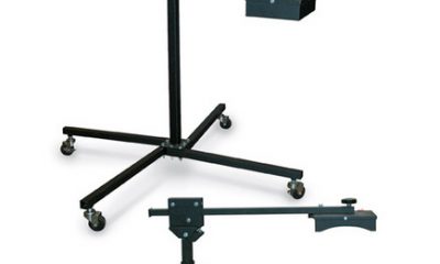
Figure 2 Thickness Gauge Contact-thickness gauges deploy their measuring probes in different ways, some using springs, others relying on pneumatic drives, and still others featuring electrically powered motors, such as the Heidenhain MT-60 shown here. The type of drive system affects the amount of control the user has over probe force during the measurement process.
By Fernando Zicarelli, Dynamesh Inc.
In this test, I used four different probe shapes/sizes: 4.8 mm flat, domed, 1.5 mm flat (also called a pin probe), and round. With each of these probes, I applied three different gauge forces: 1, 1.25, and 1.75 N. The measurement values I obtained were recorded in an Excel spreadsheet for comparison purposes.
Table 1 shows the results of this experiment. It verifies that using different probe shapes/sizes and different gauging forces does cause measurement variances, even with the same gauge. 
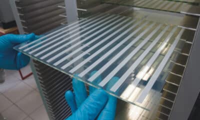
Figure 3 Measuring Thickness In the case studies discussed in this article, thickness measurements were conducted on groups of eight or 16 screens with identical thread counts, thread diameters, and tension levels. Multiple readings were taken for each screen.
Gauge type
For this portion of my study, I wanted to see if the brand and type of gauge had any impact on the measured results. I began by focusing on two spring-activated systems: the Mitutoyo model #543-252 and Heidenhain’s model #1201. I then compared the results with these systems to values recorded previously for the Heidenhain model MT-60 motorized gauge.
I used the spring-activated thickness gauges to take eight readings from the 8 x 8-in. image area of 16 separate screens. The readings were again taken from NBC monofilament polyester mesh with a thread count of 380 threads/in. and a thread diameter of 33 microns that had been stretched to a tension level of 18 N/cm2. Four probe types were used with each device: round tip, domed tip, pin tip, and flat tip. Measurement values were recorded in an Excel spreadsheet for comparison.
Tables 2A and 2B show how the probe shape affects the thickness measurement, just as it did on the motor-activated unit. The tables also demonstrate how two different gauges from two different manufacturers can provide completely different readings if the gauging force is not the same. In this test, the Mitutoyo model #543-252 used a force of 1.2 N, while the Heidenhain model #1201 used a force between 0.6-0.85 N. 
Table 1 The Impact of Probe Type and Measuring Force This table shows how the use of different probe geometries/sizes and probe forces can alter the measurement results delivered by a thickness gauge. The gauge chosen for this experiment uses an electronic motor for probe deployment and supports several probe-force levels.
However, if we compare the thickness readings from the Heidenhain MT-60 motorized gauge after it was set up to achieve a force of 1.25 N (Table 3) with the reading from the Mitutoyo model #543-252 (Table 2B), in which applied force was 1.2 N, we see that the thick-ness readings are within 1 micron of each other. The close similarity between these results is due to the fact that both gauges used nearly identical probe shapes and activation forces. This is further evidence that gauge type has little bearing on measurement results; probe shape/size and measuring force have a much more significant influence.
To complete my assessment of gauge types, I also decided to look at electromagnetic gauges, which are frequently used in the screen-printing industry for measuring dry ink-film thickness, but are increasingly being used to measure mesh and stencil thickness. Magnetic thickness gauges are lightweight devices that you can take anywhere. They operate by measuring the distance between a probe and a steel surface and can measure the thickness of any non-conductive materials placed between these two points.
For this portion of the study, I used a DeFelsko Positector 6000 SPFS magnetic thickness gauge. The device contains a magnet and a hall sensor. The hall sensor measures how the magnet reacts as it is brought closer to the steel base; the closer to the steel plate, the stronger the magnetic attraction. The gauge’s mi-croprocessor converts that magnetic value into a thickness measurement. 

Tables 2A and 2B the Impact of Gauge Type and Brand When the same screen fabric was measured with two different brands of spring-activated gauges, the values returned varied substantially for all probes except the 4.8-mm flat type. The discrepancies were primarily the result of the different probe forces applied by the devices–the gauge that produced the values shown in 2A used a pressure between 0.6-0.85 N, while the gauge represented by 2B applied a force of 1.2 N.
Magnetic-gauge accuracy is impacted by several conditions. First, if the steel base is dirty or scratched, this can affect the readings. Second, if the probe position is not held correctly, inaccurate readings again can result. Finally, the operator must take several readings to obtain an average measurement, which will be more accurate and repeatable. This gauge is designed to take a reading every 2 sec if the probe is left on the mesh, so it is best to discard the first measurement and use the second or third measurement.
I took 16 readings from the 8 x 8-in. image area of eight separate screens, again featuring NBC 380 thread/in. mesh with 33-micron thread diameter that had been stretched to 18 N/cm2. The probe was zeroed before each screen was measured, and I took three readings from each screen before lifting the probe (remember, this device takes a reading every 2 sec).
The averaging feature on this thickness gauge allowed me to record an average thickness reading of 45 microns with a tolerance of


Magazine
Get the most important news
and business ideas from Screenprinting Magazine.
-

 Case Studies2 months ago
High-Density Inks Help Specialty Printing Take Center Stage
-

 Art, Ad, or Alchemy2 months ago
F&I Printing Is Everywhere!
-
 Andy MacDougall2 months ago
Functional and Industrial Printing is EVERYWHERE!
-

 Columns3 weeks ago
8 Marketing Mistakes Not to Make When Promoting Your Screen Printing Services Online
-

 Editor's Note3 weeks ago
Livin’ the High Life
-

 Marshall Atkinson3 weeks ago
How to Create a Winning Culture in Your Screen-Printing Business
-

 Thomas Trimingham2 months ago
“Magic” Marketing for Screen Printing Shops
-

 News & Trends2 months ago
What Are ZALPHAS and How Can You Serve Them in Your Print Business?