Articles
Published
23 years agoon
Last year, Screen Printing magazine introduced readers to screen-printable electroluminescent (EL) lamps that can be used in electronics and other industrial and graphics applications. The technology, developed by EL Specialists, Plano, TX, allows the production of EL panels solely from screen-printable materials. Now the company is taking EL technology into the safety and novelty arenas, as well. Read on to discover how you can use its latest discovery–EL heat transfers–to expand the appeal and functionality of your decorated garments.
Nearly everyone has seen children’s athletic shoes that flash in various colors of light with each step that a child takes. Tiny light-emitting diodes (LEDs) embedded along with small batteries in the soles of each shoe are the source of the flashes, which are triggered by pressure from walking, running, and jumping.
Shoes and garments that emit or reflect light have proven popular not only for their novelty, but also for the safety value their high visibility provides. Today, besides LEDs in shoes, we see a variety of technologies and materials used to enhance the visibility of fire-fighting uniforms and other emergency-service clothing, options that include photoluminescent (glow-in-the-dark) as well as reflective films and inks.
However, with photoluminescent products, light emission decreases over a relatively short time (typically under 12 hours) when the material remains exposed to darkness. And reflective materials only “light up” when they are struck by light from vehicles or other sources.
Imagine an alternative that would provide the continuous-lighting benefits of an LED and the flexibility and durability of printable material. Consider the additional benefits you could realize by powering the printed material in timed intervals to create a pulsing light effect, rather than just continuous lighting. These capabilities aren’t science fiction; they’re real performance attributes of polyurethane-based electroluminescent lamps, lamps that can be combined with graphics to produce light-emitting heat transfers for application to a wide assortment of garments.
The appeal of EL
EL technology is not new to the area of safety clothing. Conventional EL films, such as those used in electronics applications, have seen some limited use by cyclists and runners. But these films are typically just small panels that are affixed to garments temporarily–they are not permanent elements of the clothing, nor do they exhibit the high flexibility one expects from a garment.
With printable EL materials, however, garment screen printers can create light-emitting designs that are flexible, durable, and permanent parts of the garments to which they are applied. This means EL designs can be optimized for particular safety applications and garment styles while providing more comfort for the wearer.
Because printers can create EL designs and patterns in virtually any configuration, the benefits of the technology extend beyond safety applications. Coupled with multifunctional power supplies, complex lighting sequences can be created that not only light up but animate garment graphics. Based on the success of other light-emitting and reflective garments, this new EL technology promises a high level of appeal when used in children’s clothing and novelty products. It’s use in promotional T-shirt graphics is also promising because it turns decorated T-shirts into highly-visible mobile maquees.
Depending on the specific light-emitting chemistry chosen, printable EL materials will give off different colors of light when powered, as well as a range of different reflective colors when unpowered in daylight. The results when used as heat-transfers for garments are images that look much like conventional graphics in daylight conditions, but “come alive” with a light show when activated in darkness.
The materials and construction methods used to create EL transfers re-sult in transferred graphics that will withstand multiple washing and drying cycles. Additionally, the small battery-operated power sources included with garments that feature EL transfers present no risk of shock (the wearer of an EL garment could safely stand under a shower while the EL design was activated).
Garments See the Light
In the past, EL panels for electronics applications were constructed using a film precoated with indium tin oxide (ITO), a transparent conductive material. This layer was then overprinted with a phosphor layer (which emits light when electrically stimulated) plus various nonconductive and conductive layers. The development of printable ITO formulations allowed users to avoid the precoated film and print the ITO, along with the other layers that make up the lamp, onto conventional films such as polyester. However, while this form of EL panel provides a flexible structure, the flexibility is limited by the base film, which cannot conform fully with the flexibility of garment fabrics.
For EL technology to gain the flexibility required in garment decorating, the base film had to be replaced. The solution was to develop a flexible, printable base layer that would perform the same function as a film.
Research and testing led to the development of elastomeric EL panels that use a polyurethane-based catalyzed ink to form the base and top layers of the completed lamp. The polyethylene layers not only provide the flexibility required, but encapsulate lamp panels, protecting them from damage and enhancing the overall durability of the lamp and graphic.
With these materials, the lamp is printed on a temporary carrier film, just as a conventional hot-split plastisol transfer is printed on a carrier sheet. When the lamp is completed, it is applied to the garment with a heat-transfer press. Depending on the transfer adhesive used with the multilayer EL graphic, the design can be applied to variety of materials, including fabrics, leather, plastic, metals, and papers.
A design incorporating EL technology can feature a single panel or multiple independent panels. In the latter case, the technology can be used to form multicolor graphics with variable patterns and EL lamp locations that can be selectively activated from a single small controller.
This controller, called an inverter, converts DC power from a battery into the AC current required to power EL lamps. Recent improvements in inverter design are one of the key developments that have made EL transfers possible. New integrated chip (IC) technology supports smaller inverter sizes and thinner profiles than ever, allowing battery powered inverters to be easily concealed within a garment.
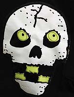
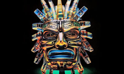
The Halloween skull design shown in Figure 1 was produced to demonstrate the printing and performance characteristics of applied EL heat transfers. Just as with printed EL panels for electronics applications, this design involved a multilayer lamp/graphic construction.
This particular design features five independent EL panels that make up the eyes and teeth of the skull. The panels are powered by a small inverter/battery pack that fits in a chest pocket adjacent to the image. The controller pulses voltage sequentially through five leads to each of the EL panels so that light appears to rotate through the teeth and eyes. The controller also allows the user to select the speed at which the light cycles through the sequence of panels.
Note that finished EL heat transfers need not be applied to garments at all. If transfers are thick enough, they can be removed from the carrier sheet and formed into three-dimensional shapes (Figure 2). Although further exploration is required, novelty products seem a good fit for this use of polyurethane-based EL lamps.
EL-transfer production
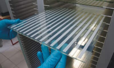
EL transfers are created using conventional screen-printing techniques. However, to get optimum light-emission from the printed materials, it’s critical to maintain a clean, dust- and moisture-free production environment.
The production process starts when a special release sheet is placed on the press bed or platen. Next, the catalyzed polyurethane ink is printed, either in clear form or in a colored version where a fluorodye (a fluorescent dye with excellent light tranmission and reflectance properties) has been added to create a smoother transition between the EL and graphic areas of the design. This layer, which extends beyond the edges of the area that will contain the EL lamp layers, is then cured.
Additional graphic layers may also be printed depending on design and color requirements. These layers are printed with polyurethane ink that has been colorized with either fluorodyes where the print will cover EL portions of the design or conventional pigments for non-EL image areas. Once these layers are printed and cured, it’s time to print the layers that make up the working portion of the lamp. In order from the front to the back of the transfer image, the sequence of layers includes the following: a conductive front bus bar printed with silver polymer thick film (PTF) ink that delivers maximum current to the ITO layer an ITO layer that delivers current to the light-emitting phosphor a phosphor layer, which emits one of several colors of light, including white, green, or blue, plus variations thereof depending on the phosphor layer’s chemical composition a barium titanate layer, which is a dielectric insulator that keeps the conductive layers of the lamp isolated a rear electrode layer (The electric field that excites the phosphor layer is generated between this electrode and the front bus bar/ITO layers.)
To complete the EL transfer, one or more layers of clear polyurethane is printed over the previous layers, extending over the EL lamp layers to make contact with the edges of the polyurethane layer on the front. The electrical leads out of the primary design area are also encased between polyurethane layers to ensure durability. The net effect is that the polyurethane forms a watertight envelop that protects the electronics within the transfer. In a final step, a conventional heat-activated transfer adhesive is applied to the completed EL graphic with a heat-transfer press.
The multistage printing process can be varied to produce different thickness for a number of product requirements. If greater mechanical strength is required, extra layers of the polyurethane can be printed on either the front or back of the transfer; alternately, fewer layers can be applied if ultimate flexibility is required. However, the polyurethane layers must provide enough mechanical support to prevent damage to the EL layers.
For the skull example, the total thickness of all layers was optimized at approximately 305 microns in thickness over light-emitting areas and 250 microns thick over the remainder of the completed transfer. Polyester screens can be used to print each layer of the transfer. Suitable mesh counts range from 64-355 threads/in., with lower counts used for the insulating layer and protective polyurethane layers and higher counts for the bus bar, graphic, and ITO layers.
The transparent ” window” over the EL areas may have to be tinted to blend with the rest of the color graphics. The fluorodye added to the polyurethane base ink must be carefully balanced to provide the desired color in daylight viewing while allowing the EL lamp(s) to emit sufficient light in dark environments. Some experimentation is needed initially to achieve a dye combination that creates the desired effects.
Designing EL transfers
EL transfer designs must incorporate both conventional graphics and the electronics (Figure 3) required to power the panels called for in the design. Conventional graphic-arts design programs (e.g,. Macromedia Freehand, Adobe Illustrator) are well suited for creating the designs and allow each layer of the EL transfer to be output as separations.
During the design process, it’s critical to work out where the power source will be situated and design the circuitry (front bus bar and rear electrode layers) so that leads are positioned in a convenient location as close to the power source as possible. Ideally, you don’t want the leads or connection points to be noticeable.
In the skull example, the design edge falls right next to the T-shirt’s chest pocket, where the inverter and batteries are located. A small opening in the seam allows the leads to protrude into the pocket, where the connection points are located.
Most electronics connectors for thin-film circuits are designed to interface with leads on more rigid polyester. The rubbery polyurethane on the leads of EL transfers requires a special connector to achieve a strong mechanical joint and good electric contact with the power source.
Product testing
What kind of performance can be expected from an EL transfer? The skull design discussed previously underwent several tests to answer this question.
The first test looked at the transfer’s resistance to temperature. The transfer process is really a two-stage process: First the transfer must resist application of the transfer adhesive, which is applied at 250°F (120°C) for 10-15 seconds. Next, the completed EL graphic was transferred to a 100%-cotton garment, also at 250°F for 10-15 seconds.
The key concern here was whether the sensitive conductive components of the transfer could survive two rapid changes from room temperature to transfer temperature. After multiple applications, no damage or diminished performance could be detected on any of the test transfers.
The next test focused on the transfers’ crush-resistance after application to the garment. Several decorated garments were manually crushed into small fist-sized balls and then flattened out repeatedly. Initially, most of the tests resulted in failure. But the latest formulation of polyurethane ink has resulted in applied transfers that will resist at least 10 such crush tests. An unconventional spin-off of this test was a truck test, were the decorated garment was laid flat on a concrete surface and a large truck rolled over it several times. None of the samples tested showed any damage after this test, either.
What happens if the surface of the transfer is damaged? This question was answered by driving a sharp metal object through one of the lit areas on the transfer while the power was on. No electrical shock resulted through the metal object, and the damaged lamp continued to operate. After several repetitions, in became clear that the only way to cause lamp failure was to completely sever the circuit near the edge of a lit zone. But even then, the other lit zones will continue to function normally.
Extreme environmental conditions were also considered. Testing involved cycling the decorated shirts from -40°F to 150°F (-40°C to 40°C), repeatedly going from one extreme to the other in 15 min, then holding at each extreme for 15 min. The sample had reached 101 cycles without failure when this test was concluded. Keep in mind that while the transferred EL graphic survived this test, the batteries used to power EL lamps are much less resistant to rapid temperature changes and could fail.
The final test involved removing the inverter/battery pack and putting several of the decorated T-shirts a washer and dryer. Each garment experienced several washing/drying cycles and all continued to function properly afterwards.
New opportunities
The processes and materials used to produce EL heat transfers are still undergoing refinements. But the prototypes discussed hear have already shown the potential of the technology. If unique apparel is your specialty, producing and applying EL transfers may be a new application in which your business can shine.


Subscribe

Magazine
Get the most important news
and business ideas from Screenprinting Magazine.
Most Popular
-
 Case Studies2 months ago
High-Density Inks Help Specialty Printing Take Center Stage
-

 Art, Ad, or Alchemy2 months ago
F&I Printing Is Everywhere!
-
 Andy MacDougall2 months ago
Functional and Industrial Printing is EVERYWHERE!
-

 Columns3 weeks ago
8 Marketing Mistakes Not to Make When Promoting Your Screen Printing Services Online
-

 Editor's Note3 weeks ago
Livin’ the High Life
-

 Marshall Atkinson3 weeks ago
How to Create a Winning Culture in Your Screen-Printing Business
-

 Thomas Trimingham2 months ago
“Magic” Marketing for Screen Printing Shops
-
 Case Studies3 weeks ago
Screen Printing for Texture and Depth