Within the last few years, Radio Frequency Identification (RFID) technology has developed substantially. Prior to this period, lack of production standards and an infrastructure to support different RFID applications gave this innovation a doubtful technological start.
Within the last few years, Radio Frequency Identification (RFID) technology has developed substantially. Prior to this period, lack of production standards and an infrastructure to support different RFID applications gave this innovation a doubtful technological start.
Persistence by RFID developers, however, has led to breakthroughs in production systems, and supply channels have evolved to support RFID manufacturing. Currently, most RFID applications are standardized, and the market for these products has seen a significant increase in the number of companies that produce them.
Among the companies who have been exploring the market for RFIDs are businesses with a background in industrial screen printing, particularly those who have experience in electronics printing. But companies employing other printing process also have made inroads into various aspects of RFID manufacturing. In this article, we’ll look at what RFIDs are and how they function. We’ll also find out how screen printing and other imaging technologies are proving ideal for producing a key component of RFID tags and labels—their antennas.
Principles of RFID
In basic terms, RFID technology was created to make the process of identifying and tracking products simple, fast, and accurate. Other benefits and capabilities provided by RFID tags and labels include the ability to
Advertisement
• protect product authenticity
• protect products against theft
• control product inventories in retail outlets, warehouses, libraries, etc.
• control access to buildings, car parks, roads, and other locations
• increase the speed of data processing while lowering its cost by preventing errors from occurring during data entry
Before RFIDs, barcodes on product packages and magnetic strips on banking and security cards were the primary ways in which products and transactions were identified and tracked. Accessing the data represented by a barcode or magnetic strip requires the item or card to be scanned by a reading device. The product or card must be manually positioned in the device, which can lead to delays in data processing. We’ve all experienced these delays at airline ticket desks and at the checkout counter in the local supermarket.
RFID technology provides an automatic means of delivering data about a product or account without direct contact between the RFID label, tag, or card and the reading device. RFIDs react to magnetic radiation by returning data to the reading device about the product or card to which they’re attached. Additionally, the data stored on some RFID tags can be updated or changed. While RFIDs are unlikely to completely replace all barcodes and similar systems, they are poised to become the dominant form of product identification in the future.
The makeup of an RFID tag is basically the same whether it is used as a label that is affixed to a product or embedded in a credit or banking card. The tag contains an RFID transponder, which consists of a chip attached to an antenna. The antenna is actually a simple coil, generating magnetic induction or an electric voltage.
The data exchange between the RFID tag and the antenna of the reader/writer takes place without direct contact between the reader and the tag. The reader/writer is connected to a computer. The following is a step-by-step description of how RFID technology works:
1. The passive RFID tag is moved within the electromagnetic field of a reader.
2. The tag receives a signal from the reader, which activates the tag.
3. The tag responds by transmitting to the reader data saved on the transponder’s chip.
4. The reader passes on the received data to the main computer. The reader also may provide the tag with new data, overwrite existing data, or deactivate the tag.
Advertisement
One considerable advantage of the RFID tag over a barcode is that the tag can be read without being in the line of sight of the reading device. Unlike the barcode, no human assistance is required to position an RFID tag so that it can be read—the process of reading the tags can be executed automatically.
Another advantage of RFID tags is that the chip on an RFID transponder is a dynamic data carrier, meaning that data can be both be read from and written to the chip. And because the data are exchanged via electromagnetic radiation, multiple RFID tags can be read simultaneously.
Currently RFID tags are seeing increased use for logistic and supply- chain management by postal and courier services, the food industry, the medical care and the pharmaceutical industries, and libraries, as well as in access management and toll collection, airline baggage handling, cattle identification, document tracking, and product authentication or anti-counterfeiting. To protect clothing against counterfeiting and theft, some companies are even working on means to print RFID antennas directly on textiles.
Types of RFID tags
RFID tags come in two forms: passive and active. Passive RFID tags require activation by means of the reader system before transmitting the data they carry. Active RFID tags are provided with a battery, which enables them to transmit signals independently. For this article, we will focus only on passive RFID systems, which are the most common type.
The antennas of passive RFID tags can generate an inductive or a capacitive signal. An inductive antenna is able to convert a magnetic field into an electrical signal, or the other way around. These antennas look like a wound coil. The counterpart is the capacitive antenna. This antenna is not susceptible to electromagnetic energy, but only electrical signals. A capacitive antenna is recognizable by its dipole shape (Figure 1).
Advertisement
The frequency of the electromagnetic radiation determines the read distance that the tag will support. The minimum read distance required to collect the data is a major influence on the design of RFID antennas for specific applications.
RFID tags can be based on a number of frequency bands, such as low frequency (LF), high frequency (HF), ultra-high frequency (UHF), and microwave (Table 1).
|
Table 1 Frequency of RFID Tags
|
|
Band
|
Frequency
|
Read/write distance
|
|
LF
|
125 kHz
|
less than 20 in.
|
|
HF
|
13.56 MHz
|
approximately 3 ft
|
|
UHF
|
862-950 MHz
|
16 ft or more
|
|
Microwave
|
2.45 GHz and 5.8 GHz
|
approximately 3 ft
|
The read and write distance of RFID tags ranges from 4 in. (10 cm) to more than 16 ft. (5 m).
LF antennas support a frequency of 125 kHz. They consist of coiled copper wire that is wound 200 times or more. LF tags are used for relatively short read distances—not exceeding 20 in. (50 cm). Common applications for LF tags include access control (i.e., door-entry/security cards) and identification of cattle and other livestock.
HF tags are equipped with antennas consisting of four to six windings of copper coil and are sensitive to a frequency of 13.56 MHz . These tags support a maximum read distance of 3.25 ft (1 m). HF tags are used for "smart cards," such as those issued by libraries and for luggage tags in airline baggage-handling systems.
UHF tags respond to a frequency range of 862-950 MHz and have a read/write distance of 16 ft or more. In the US, the UHF standard frequency is 915 MHz. In other parts of the world, different frequencies may be used. The large read distance requires a dipole antenna. Such tags allow postal and courier services to determine the nature of the products piled up on a pallet without having to inspect each package individually. These tags are also used in cards issued to motorists for automatic toll collection.
The microwave RFID tag has a read distance of approximately 3.25 ft and responds to frequencies of 2.45 or 5.8 GHz. Microwave RFID tags are used for logistics applications.
HF and UHF tags are the most popular RFID systems. These tags consist of three main components:
• Antenna—the silver, copper, or aluminum antenna communicates with the reader by transmitting and receiving data.
• Chip—the chip is mounted on the antenna and stores data for transmission.
• Inlay—an inlay is the assembled chip and antenna on a carrier sheet. The RFID inlay can be placed on adhesive paper or plastic to function as a label or tag, or it can be mounted on a plastic card.
Producing RFID Antennas
Manufacturing the antenna is the initial step of the RFID production process. Antennas for HF and UHF RFID tags can be produced in three different ways:
• direct printing with a silver conductive ink
• removing copper or aluminum from a laminate by etching (subtractive method)
• applying an electrically conductive medium and then galvanizing it (additive method)
Each of these methods for manufacturing RFID antennas can be accomplished with a printing process. Depending on the run length and the characteristics required from the antenna, flexography, gravure printing, or screen printing may be used (Table 2).
|
Table 2 Comparison of Antenna-Printing Methods
|
|
Characteristic
|
Screen printing
|
Flexo/gravure
|
|
Investment
|
low to medium
|
medium to high
|
|
Print speed
|
low to high
|
medium to very high
|
|
Ink-deposit thickness
|
variable
|
low
|
|
Run length
|
very short to medium
|
large to very large
|
Direct printing Direct printing allows antennas to be produced in one pass, whereas the other methods require multiple steps. In direct printing, a solvent-based, conductive, silver polymer-thick-film (PTF) ink is used to print the antenna on a plastic or paper substrate (Figure 2). UV inks for this application are currently in development.
HF antennas require a relatively thick ink deposit to provide the proper level of conductivity, so screen printing is a leading technique for producing these antennas. Screen printing is an ideal technique for delivering a measured deposit of ink. And the deposit thickness can be easily modified by switching to a mesh with a different thread count. After printing, hot-air drying causes the silver particles in the ink to become connected, which creates an electric circuit—the final antenna.
In addition to PTF inks, thermal silver conductive inks also are available. These inks don’t contain a polymer binder; instead, they contain electrically conductive organo-metallic particles. These particles are melted together under high temperature. Antennas printed with thermal silver conductive inks provide greater conductivity than those produced with PTF inks.
UHF antennas are basically thinner than HF ones. Consequently, other printing methods may be more suitable than screen printing for producing UHF antennas. Flexography and gravure printing both deposit significantly less ink than screen printing, but enough for UHF antennas. These print methods are typically used with jobs involving longer run lengths.
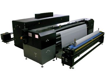
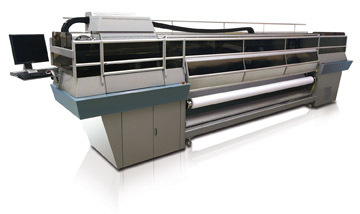
Flexography and rotogravure print with a speed of 100-500 ft/min (30-150 m/min). The speed of flatbed screen- printing equipment is far slower, so flatbed screen presses generally just are used for producing prototypes and very small jobs. Rotary screen printing, on the other hand, delivers speeds of approximately 80-200 ft/min (25-60 m/min), which puts it prominently in the middle between flatbed screen printing and flexo/gravure. The performance attributes of both flatbed and rotary screen printing are compared in Table 3.
|
Table 3 Comparison of Screen-Printing Methods
|
|
Characteristic
|
Flatbed
|
Rotary
|
|
Print speed
|
low
|
high
|
|
Substrate
|
sheet
|
web
|
|
Run length
|
prototype and very short
|
short to medium
|
Rotary screen printing, flexo, and gravure are excellent techniques to manufacture large quantities of RFID antennas reel-to-reel. The run length of UHF antennas determines the most suitable print technique. Generally, two passes are required to print HF antennas using flexo and gravure, compared to one pass using rotary screen printing. Since double-pass production introduces the possibility of registration problems, rotary screen has become a dominant method for producing HF antennas in all run sizes. It also is used for short to medium run lengths of UHF antennas.
The subtractive method
For the subtractive method of RFID antenna production (sometimes called the print-and-etch method), the substrate is a laminate consisting of a plastic base material, such as polyester, covered with a layer of copper or aluminum that is 20-25 microns thick. A mask of etch resist is screen printed on the metallic surface of the laminate. This mask is a positive copy of the shape of the antenna, and it protects the metal underneath from being attacked by the etching agent (Figure 3). When the aggressive etching agent is applied, the agent dissolves the copper or aluminum that is not covered by the mask. Next, a stripping solution is applied to remove the mask, and the finished antenna remains (Figure 4).
The additive method
The additive method (also called the print-and-plate method) is similar to the subtractive method. It involves applying a thin deposit (a few microns) of conductive catalytic ink in the positive shape of the antenna onto a plastic substrate. This special ink contains metal particles. After the ink is applied, the printed material undergoes a galvanic process in which copper is plated onto the substrate, adhering only to the pattern created by the conductive ink. The process continues until the amount of copper deposited on the substrate reaches a thickness that provides the proper level of conductivity.
The future of RFID technology
Because the price of chips used in RFID devices is still relatively high, the use of RFID in the near future will be limited to niche applications for multiple-use HF tags. Such applications will include personal identification products, as well as tags for tracking books and documents. Rather than being used for single-product identification, long-range UHF tags will find use in logistics applications such as tagging boxes, pallets, and containers of multiple products.
As the demand for RFID tags and labels increases, the price of the chips used in these devices will come down. Consequently, we can expect to see applications for RFID technology expand. RFID specialists expect a substantial increase in the use of RFID products to occur between 2010 and 2015. When that time comes, the effectiveness that screen printing already has shown in producing antennas for RFID tags guarantees the process a bright future in this market.
About the author
Wim Zoomer is owner of The Netherlands-based Technical Language, a consulting and communication business that focuses on screen printing and other printing processes. He has written numerous articles for industry journals and is frequently called on to translate technical documents, manuals, books, and marketing materials between English, French, German, Spanish, and Dutch. He recently completed a book entitled Printing Flat Glass. For more information, visit Zoomer’s Website at www.technical language.eu.


 Case Studies2 months ago
 Art, Ad, or Alchemy2 months ago
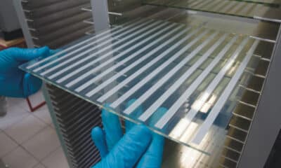
 Andy MacDougall2 months ago
 Columns3 weeks ago
 Editor's Note3 weeks ago
 Marshall Atkinson3 weeks ago
 Thomas Trimingham2 months ago
 News & Trends2 months ago